00193370-0202.pdf - 第48页
Handbuch für das Achsprüfgerät / Axis T ester Manual SIPLACE Axis T e ster 2 The axis tester and it s components Ausgabe 08/2003 Edition 48 2 The axis tester and it s component s Fig. 2 - 1 Axis tester - plan view M 240 …

SIPLACE Axis Tester Handbuch für das Achsprüfgerät / Axis Tester Manual
Ausgabe 08/2003 Edition 1 Overview
47
1Overview
To optimize your placement machine’s performance, you must first optimize the dynamic re-
sponse of the axes. Signals from the axis controller are tapped using an adapter board so that
they can be used for tests, settings and diagnosing errors. An oscilloscope connected to the
adapter board displays the signal traces for your diagnostics.
The new SAT (S
IPLACE Axis Tester) greatly simplifies the test set-up. There is just one ribbon
cable connecting the axis tester to the axis board. The tester can be connected to series A360,
A361 and A362 axis cards. The signal traces can be graphically represented on the display. The
tester can also read the register contents of counters in the axis controller board for diagnostic
purposes in order to identify counting errors by incremental position measuring systems, for ex-
ample.
The axis tester has “hot-plug” capability, which means that it can be connected to the axis control-
ler board without having to switch the machine off first.
The axis tester does not require a separate power supply. Instead, the control unit provides the
necessary + 5 VDC and ± 15 VDC voltages via the sockets on the axis controllers.
For communication, the axis tester has a CAN bus and a serial port. The CAN bus connection can
be used to send control signals to the head board or to check the status of these signals for diag-
nostic purposes, for example. The signals can be output for further analysis to measuring devices,
such as oscilloscopes, voltmeters, etc, via four freely assignable BNC sockets. The positioning
movements of the axes and other data that appears on the axis tester display can also be sent to
a plotter and printed out for documentation purposes.
A user-friendly menu structure allows the axis tester to be quickly configured for all required diag-
nostic tasks. Preprogrammed configurations tailored to each type of placement machine greatly
reduce the time required to build the test set-up and take the measurements. You can also store
your new test configuration for later use.
Handbuch für das Achsprüfgerät / Axis Tester Manual SIPLACE Axis Tester
2 The axis tester and its components Ausgabe 08/2003 Edition
48
2 The axis tester and its components
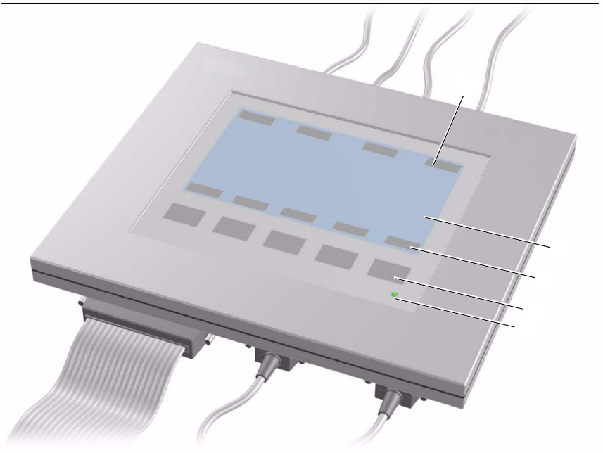
Fig. 2 - 1 Axis tester - plan view
M 240 x 128 pixel LCD display, black and white, backlit
The menus appear on the LCD display and the recorded trigger, track and position signals are
displayed graphically. All the relevant parameters, such as
- time base,
- measured times,
- amplitude scaling,
- signal level and
- cursor positions with the associated time differences
appear as alphanumeric information over the graphical representation of the measured curves.
N Dynamic function display for the BNC panel assignments on the LCD display
O Dynamic function display for the membrane key assignments on the LCD display
P Five membrane keys for menu control
Q Green operating display LED
N
M
O
P
Q
SIPLACE Axis Tester Handbuch für das Achsprüfgerät / Axis Tester Manual
Ausgabe 08/2003 Edition 2 The axis tester and its components
49
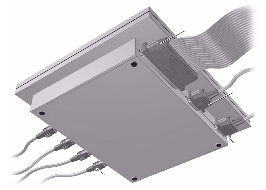
Fig. 2 - 2 Axis tester – bottom view
M Connection for ribbon cable
Connection on the axis tester: 37-pin sub-D connector
Connection on the axis controller:
– 37-pin sub-D connector for S-20/23/25/F4/F5 and HS-50 machines with A361 or A362 axis
controllers
– 25-pin sub-D connector for S-15/F3, G and wafflepack changer machines with A360 axis
controllers
An adapter is attached to the ribbon cable in order to connect the 25-pin axis controller.
The axis controller supplies the
+ 5 VDC ± 5 % and
± 15 VDC ± 5 %
operating voltages to the axis tester via the 37-pin ribbon cable.
N 9-pin sub-D connector for the CAN bus cable, e.g. for connecting CAN bus-controlled boards
in the placement machine (transmission speed 128 kBaud to 1 Mbaud, impedance 120 Ohm).
O 9-pin sub-D connector for the serial interface cable (V24), e.g. for connecting an external PC
(max. transmission speed 188 kBaud).
P Four BNC sockets, impedance 50 Ohm
The sockets can be assigned as required with the following signals:
M
N
O
P