00193370-0202.pdf - 第77页
SIPLACE Axis T est er Handbuch für das Achsprüfgerät / Axis T est er Manual Ausgabe 08/2003 Edition 8 Using the menus 77 Fig. 8 - 43 T est res ult s for the distance measurement Up to eigh t statuses may be displaye d. F…
Handbuch für das Achsprüfgerät / Axis Tester Manual SIPLACE Axis Tester
8 Using the menus Ausgabe 08/2003 Edition
76
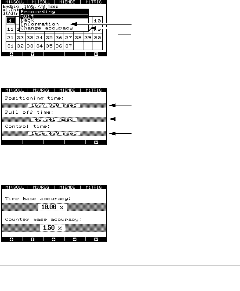
Fig. 8 - 40 Window for displaying the measuring accuracy
Æ Select the “Information” menu option. The test results are displayed.
Fig. 8 - 41 Test results for the distance measurement
Æ Select the “Change accuracy” menu option to change the permitted scatter of the time base or
counter.
Fig. 8 - 42 Setting the accuracy of the time base and counter
PLEASE NOTE: 8
Do not change the default values. 8
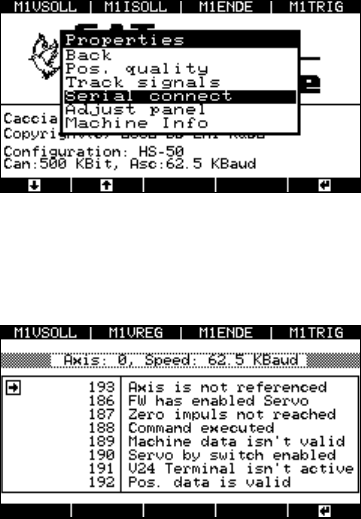
8.4.5 “Serial connect” menu
Æ Select the “Serial connect” option from the “Properties” menu.
Displays the test results
Selects the level of measuring accuracy
Duration of the end signal
Pull-off time
Trigger time
SIPLACE Axis Tester Handbuch für das Achsprüfgerät / Axis Tester Manual
Ausgabe 08/2003 Edition 8 Using the menus
77
Fig. 8 - 43 Test results for the distance measurement
Up to eight statuses may be displayed.
Fig. 8 - 44 Status display for the axis controller
The axis tester reads the statuses from the axis
controller’s register, and outputs the controller’s
status to a window with the status numbers used
on the placement machine’s user interface.
Serial connection
Left-hand window: Position display
Right-hand window: Status display for the selecte
d
axis. The information differs for each axis.
Handbuch für das Achsprüfgerät / Axis Tester Manual SIPLACE Axis Tester
8 Using the menus Ausgabe 08/2003 Edition
78
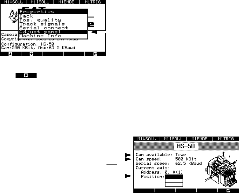
8.4.6 “Adjust panel” menu
This menu is used to adopt the settings for the current axis for all the other axes.
Æ Select the “Adjust panel” option from the “Properties” menu.
Fig. 8 - 45 “Adjust panel” menu
Press to confirm your settings.
8.4.7 “Machine info” menu
This menu indicates the currently selected axis controller.
Æ Select the “Machine info” option from the “Properties” menu.
Fig. 8 - 46 “Machine info” display
The settings for the current axis are adopted.
The CAN interface is ready
Transmission speed
Top axis controller in the 1st axis controller
board with address bus no. 0