00193370-0202.pdf - 第64页
Handbuch für das Achsprüfgerät / Axis T ester Manual SIPLACE Axis T e ster 8 Using the menus Ausgabe 08/2003 Edition 64 Fig. 8 - 10 “Pane l ” menu, “Ac tivate panel” option Æ Select th e “Activate panel ” menu opti on an…

SIPLACE Axis Tester Handbuch für das Achsprüfgerät / Axis Tester Manual
Ausgabe 08/2003 Edition 8 Using the menus
63
Each axis controller module contains three axis controllers. They are counted starting from the
topmost axis controller, i.e. all the signals from the topmost axis controller starting at 1. The ab-
breviations used are as follows:
Æ Press to select the required signal.
Æ Assign the signals to the desired BNC sockets for the entire selection group.
Æ Press to move to the next menu.
*) 1 = Top axis controller, 2 = Middle axis controller, 3 = Bottom axis controller
1/2/3 VS
*)
V
setpoint
Setpoint voltage
1/2/3 IS
*)
I
actual
Actual current for
DC motor
1/2/3 VR
*)
V
REG
Total current for
three-phase AC motor
drive
1/2/3 DI
*)
Diagnostics pin
PW0 Pulse width-modulated signal for representing the
position deviation after the end signal from axis con-
troller 1
BNC 1 assigned
PW1 Pulse width-modulated signal for representing the
position deviation after the end signal from axis con-
troller 2
BNC 2 assigned
PW2 Pulse width-modulated signal for representing the
position deviation after the end signal from axis con-
troller 3
BNC 3 assigned
PW3 Pulse width-modulated signal, variable assignment BNC 4 assigned
- 10 - 10 VDC reference voltage
5 +5 VDC reference voltage
BNC BNC test input
GND Ground
1/2/3 IN
*)
Zero pulse (index)
1/2/3 EN
*)
End signal
1/2/3 TR
*)
Trigger signal
1/2/3 LA
*)
Track signal A (line A)
1/2/3 LB
*)
Track signal B (line B)
Handbuch für das Achsprüfgerät / Axis Tester Manual SIPLACE Axis Tester
8 Using the menus Ausgabe 08/2003 Edition
64
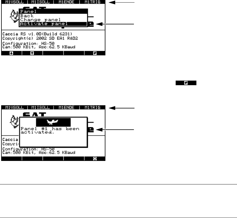
Fig. 8 - 10 “Panel” menu, “Activate panel” option
Æ Select the “Activate panel” menu option and press membrane button .
This activates the signaling line and updates the panel assignment display in the header.
Fig. 8 - 11 “Panel” menu, activation display
PLEASE NOTE: 8
Don’t forget to store your settings, otherwise they will be lost when you remove the ribbon
cable. 8
Æ From the main menu, select
- the “System control” menu
→ “Settings” → “Save” or
- the “Shutdown” menu
→ “Shutdown computer: Yes”.
8.3.2 “Config unit” menu
The “Config unit” menu is used to set the time base for sampling the signals for each of the three
axis controllers on an axis controller board. You can also set the minimum time between two pulse
edges during which a pulse train can still be triggered. In the event of overspeed, the individual
pulses can no longer be triggered and counted since the pulse train is too large. A signal and an
error message are output.
Æ Select the “Config unit” option from the “Configuration” menu.
Panel assignment display
Activates the selected assignment
Updated panel assignment display
This window indicates that the panel as-
signment has been activated.
SIPLACE Axis Tester Handbuch für das Achsprüfgerät / Axis Tester Manual
Ausgabe 08/2003 Edition 8 Using the menus
65
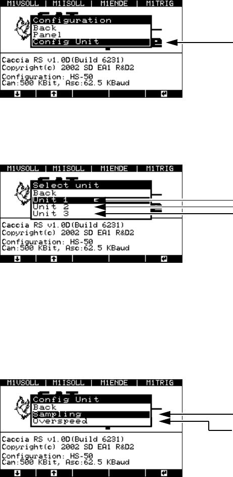
Fig. 8 - 12 “Configuration” menu, “Config unit”
The “Select unit” menu appears.
Fig. 8 - 13 “Select unit” menu
8.3.2.1 “Sampling” menu
Æ Select the required axis controller
The menu for setting the sampling frequency or maximum sampling frequency appears.
Fig. 8 - 14 “Config unit” menu, “Sampling”
Æ Select the “Sampling” menu.
The window for setting the sampling frequency appears.
“Config unit” menu
Sets the sampling values for axis controlle
r
1 (top),
2 (middle) or
3 (bottom)
Menu for setting the sampling frequency
Menu for setting the maximum sampling fr
e-
quency for the minimum time between the
corresponding edges of two successive
pulses.