D-serie LEVEL II.pdf - 第101页
Gantry Description of Boards at Gantry Settings S tude nt Guide Advanced Level 2 SIPLACE D Series EN 05/2007 Gantry 6-15 Description of LEDs on the Gantry Head Di stributor SM = stepping motor Legend PCB labeling Operati…
Gantry
Settings Description of Boards at Gantry
Student Guide Advanced Level 2 SIPLACE D Series
Gantry EN 05/2007
6-14
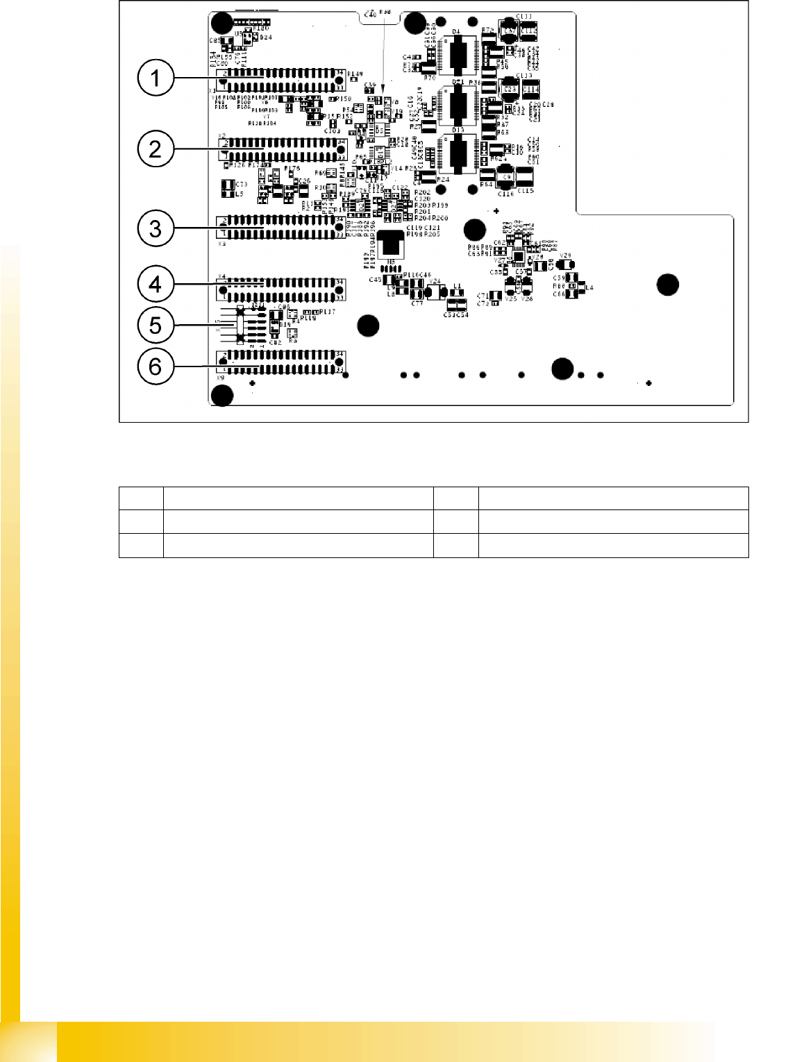
6-9: Gantry head distributor (from below)
Legend
See also:
J 8-Fold DIP Switch of the Gantry Head Distributor (incl. Switch S1) – C&P6/12 [J8-19]
J DIP Switch on Gantry Head Distributor [J6-17]
1 X1 flat ribbon cable 4 X4 not connected
2 X2 flat ribbon cable 5 X15 connector for X-axis track signals
3 X3 flat ribbon cable 6 X9 flat ribbon cable
Gantry
Description of Boards at Gantry Settings
Student Guide Advanced Level 2 SIPLACE D Series
EN 05/2007 Gantry
6-15
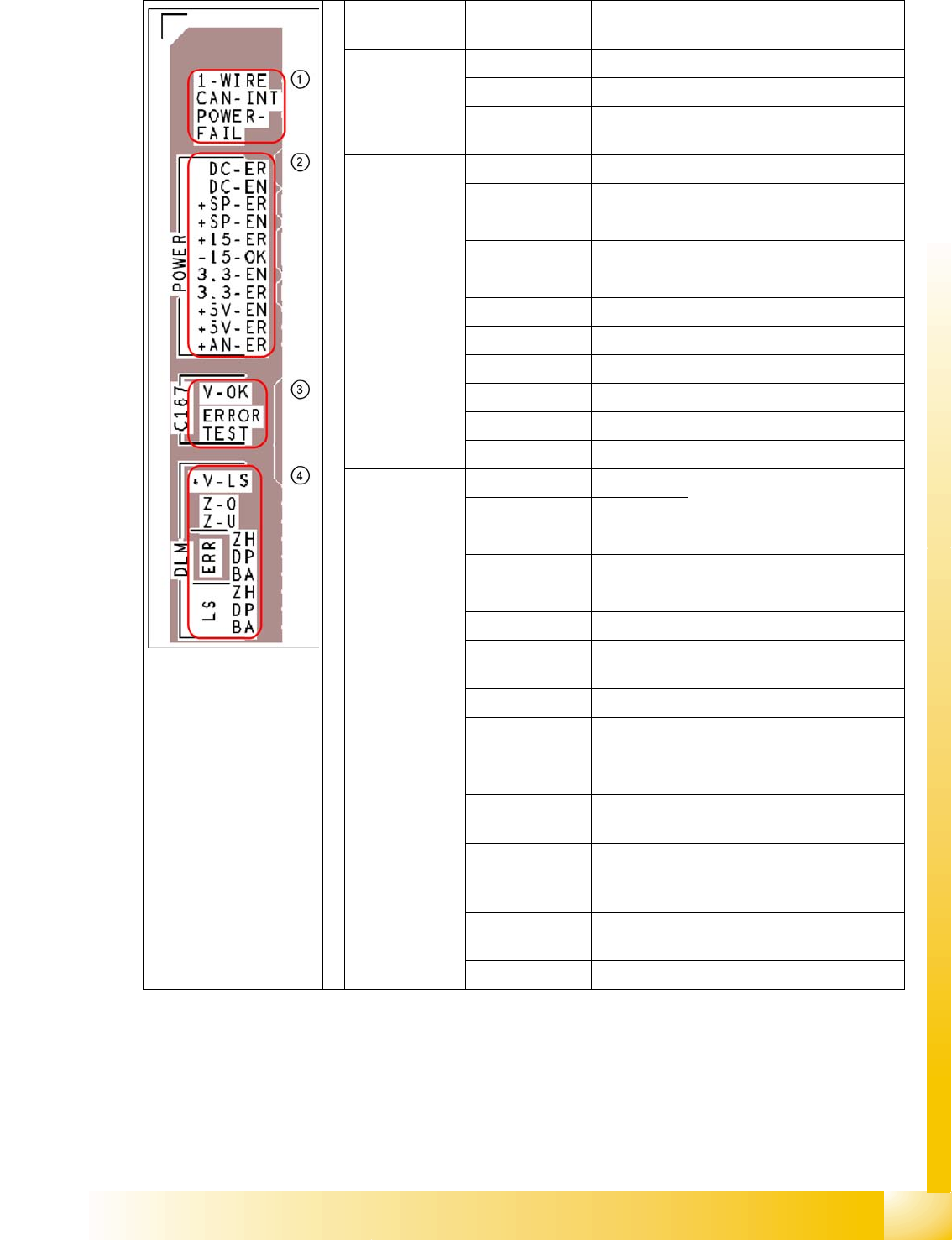
Description of LEDs on the Gantry Head Distributor
SM = stepping motor
Legend PCB labeling Operating
state LEDs
Description
1
CAN Bus
1-WIRE Not in use
CAN-INT OFF not used
POWER-FAIL OFF Error +24 V power supply (from
the main machine)
2
Status:voltage
supply
DC-ER OFF Error DC/DC converter
DC-EN ON Enable DC/DC converter
+SP-ER OFF Error +5V track encoder
+SP-EN ON Enable +5V track encoder
+15-ER OFF Error +15V
-15-OK ON -15V is OK
3.3-EN ON Enable +3.3V digital
3.3-ER OFF Error +3.3V digital
+5V-EN ON Enable +5 V digital
+5V-ER OFF Error +5V digital
+AN-ER OFF Error analog supply C167
3
Head CAN
processor
V-OK ON Internal voltage monitoring of
eSW
V-OK OFF
ERROR OFF Error eSW
TEST Flashing Timer eSW in operation
4
C&P head
functions and
signals
+V-LS ON OK + 15V light barrier
+V-LS OFF Error +15V light barrier
Z-O ON Z-axis is not up (in fork light
barrier)
Z-U ON Z down has switched
ERR-ZH OFF Overload SM valve positioning
drive, pick and place
ERR-DP OFF Overload SM swivel in, DP axis
ERR-BA OFF Overload SM valve adjustment
drive, reject
LS-ZH ON Light barrier SM valve
adjustment drive, pick and
place
LS-DP ON Light barrier SM DP axis,
swivel in
LS-BA ON Light barrier SM reject
Gantry
Settings Description of Boards at Gantry
Student Guide Advanced Level 2 SIPLACE D Series
Gantry EN 05/2007
6-16
6.3.3.2 Vision Processor Board (Digital)
The Vision processor board is mounted on the gantry head distributor board. This PCB is used for all
four gantries.
See also:
J DIP Switch on Vision Board [J6-17]
6.3.3.3 CAN 16 Bit Processor Board (TQ Module)
Description of 7-segment display (normal operation "." flashes):
After switch ON the machine appears " 0 " on the display
Display "b" --> BIOS was started.
Display flashes alternatively between "b" and "." --> no application available or unable to start
application.
Display " -I " and " I- " application was loaded.
"." flashes on the display --> ready for operation.
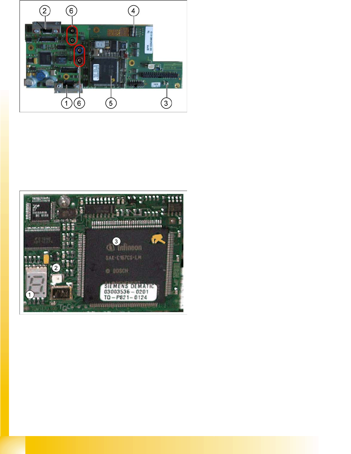
6-10: Vision processor board
Legend
1. X8 Connector illumination and video signals
PCB camera
2. X3 Connector illumination and video signals
component camera
3. LED‘s P15V - 15Volt / Vcc - Power supply
Vision board
4. DIP switch
5. CAN Processor 16 Bit (TQM Module)
6. Connector X22 - X24 Connectors for the video
cable to the trailing cable
6-11: 16 bit processor (TQ module)
Legend
1. 7 Segment display
2. LED for manual RESET of processor
3. 16 Bit Processor
The 16 BIT CAN processor is used for various
different functions in the following units:
(see chapter Communication and Control as well)
Vision board, communication and control via
the CAN Bus to the vision computer.
Gantry head distributor, control of head
processes and vacuum