D-serie LEVEL II.pdf - 第164页
Component Handling Pneumatic Tape Cutter Function Test for Tape Cutter in the Machine S tuden t Guide Advanced Level 2 SIPLACE D Series Component Ha ndling EN 05/2007 9-14 9.4.3 Function T est for T ape Cutter in the Mac…
Component Handling
Structure and Function of the Pneumatic Tape Cutter Pneumatic Tape Cutter
Student Guide Advanced Level 2 SIPLACE D Series
EN 05/2007 Component Handling
9-13
9.4.2.1 Technical Data
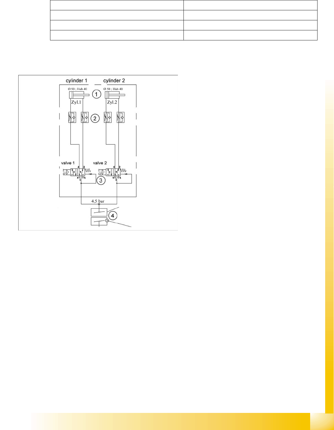
9.4.2.2 Pneumatic Scheme Tape Cutter
Compressed air supply 0.5 MPa = 5.0 bar
Compressed air consumption 135 l/min.
Cycle time 1.5 sec per cut
Supply voltages 5 VDC, 24 VDC
9-10: Compressed air supply tape cutter
Legend
1. Drive cylinder for cutter blade movement
40 mm stroke
2. Adjustable throttle valve on the pneumatic
cylinder
3. 5/2 way magnetic valve
4. 4.5 bar compressed air supply and 24 V
voltage supply via the PCC safety relay
Cutter only active when protective hoods are
closed
Component Handling
Pneumatic Tape Cutter Function Test for Tape Cutter in the Machine
Student Guide Advanced Level 2 SIPLACE D Series
Component Handling EN 05/2007
9-14
9.4.3 Function Test for Tape Cutter in the Machine
Since the noise of the tape cutter does not indicate whether the cutting procedure is being performed
correctly, the function of the tape cutter can only be checked by inserting a piece of paper with the
relevant length into the cutting channel.
X To prepare the test, use an adhesive strip to attach a sheet of DIN A4 paper lengthwise into the
empty tape duct.
X Now start the SITEST menu Component Table and activate the option "Actuate tape cutter".
X You can then examine the cutting quality on the sheet of paper.
9.4.4 Jumper Setting on the Tape Cutter Control Unit
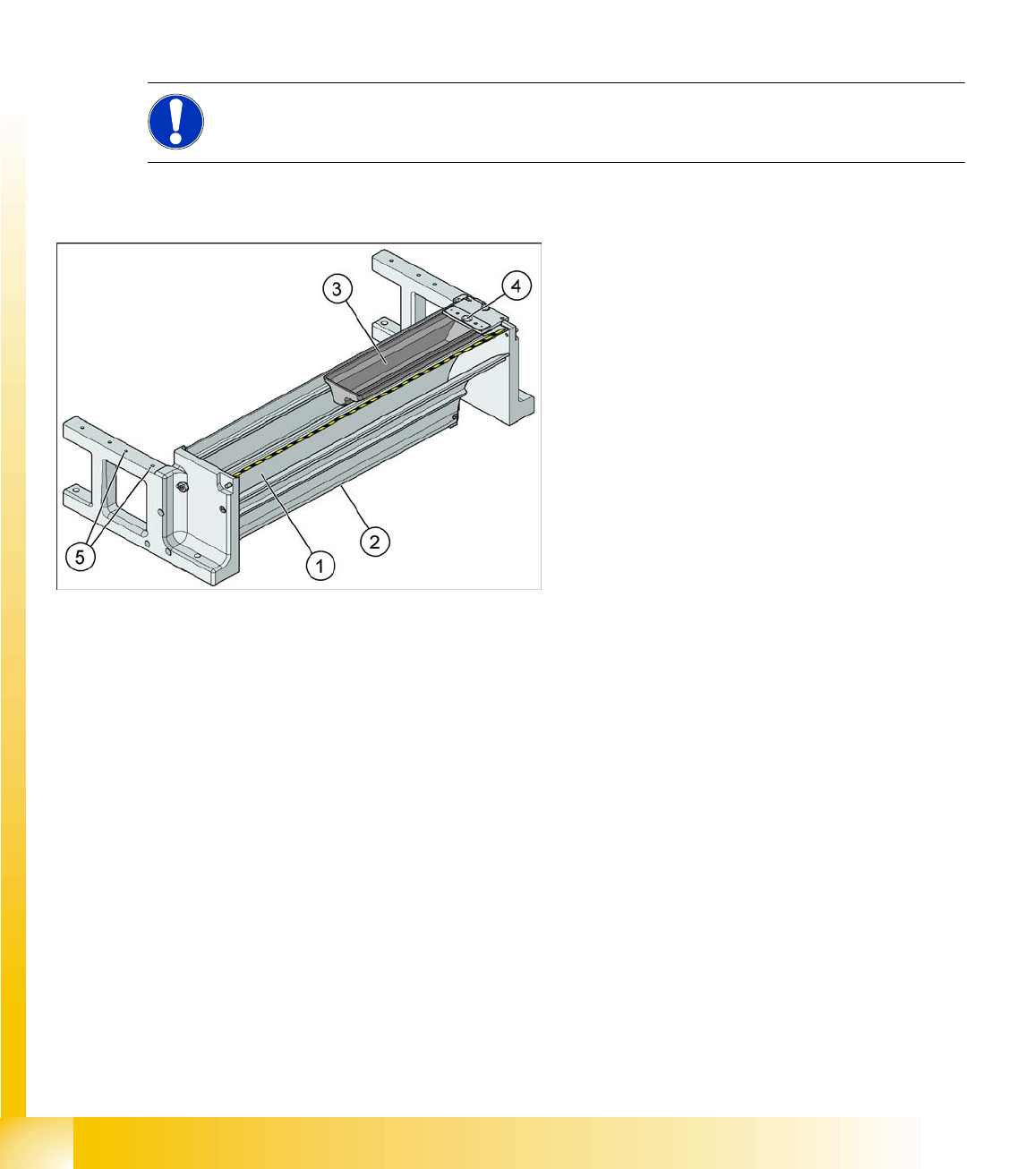
9.4.5 Empty Tape Duct
The empty tape duct acts as a base for further modules:
The removable nozzle reject container (3)
The installation surface (5) for the C&P nozzle changer
The nozzle stripping unit (4)
NOTE:
For jumper setting details, refer to the service manual for the respective machine.
9-11: Empty-tape duct with component reject container (D4 shown as
example)
Legend
1. Inlet slot for empty tape
2. Outlet slot for the empty tape above the
pneumatic tape cutter
3. Nozzle reject container
4. Nozzle reject station
5. assembly surface for the nozzle changer
The empty tape duct receives empty tapes from
the feeders at the inlet gap (1) and guides these
from the outlet gap (2) to the cutting position of the
pneumatic cutter. This is where the tape is cut up
and falls down the waste slide, into the component
trolley waste tape container.
The empty tape duct is fixed to the pneumatic tape
cutter with four screws.

Component Handling
Empty Tape Duct Room for Your Sketches and Notes
Student Guide Advanced Level 2 SIPLACE D Series
EN 05/2007 Component Handling
9-15
9.5 Room for Your Sketches and Notes