D-serie LEVEL II.pdf - 第99页
Gantry Description of Boards at Gantry Settings S tude nt Guide Advanced Level 2 SIPLACE D Series EN 05/2007 Gantry 6-13 6.3.3 Description of Boards at Gantry The following PCBs at the g antry are in principle i dentical…
Gantry
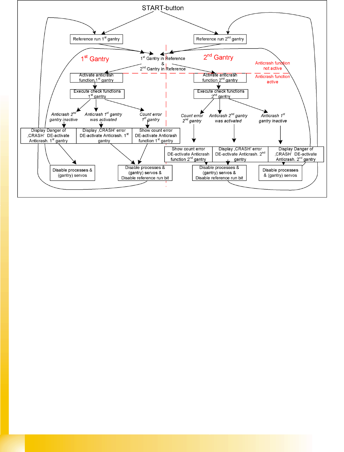
Settings Anticrash Function for the A364 Axis Controller Board
Student Guide Advanced Level 2 SIPLACE D Series
Gantry EN 05/2007
6-12
6.3.2.5 Anticrash Function
Gantry
Description of Boards at Gantry Settings
Student Guide Advanced Level 2 SIPLACE D Series
EN 05/2007 Gantry
6-13
6.3.3 Description of Boards at Gantry
The following PCBs at the gantry are in principle identical and independent of the head configuration in
D1, D2 and D4 machines (the D3 has a different board here). The CAN bus terminating resistor is fixed
onto the gantry head distributor.
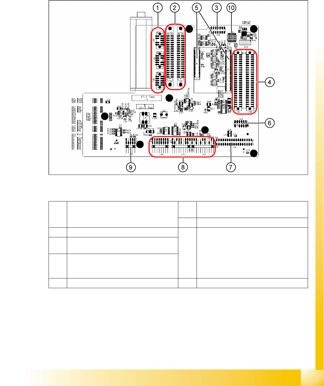
6.3.3.1 Gantry Head Distributor
6-8: Gantry head distributor (from above)
Legend
1 X20 stepping motor reject position
X19 stepping motor pickup/place
X18 stepping motor DP axis, swivel in
6 X24 test connector "digital track signals for X-
axis"
7 X29 Vision board connector
2 X13/X14 flat ribbon cable to C&P head 8 X10 vacuum measurement board connector
X12 motor for DP axis
X16 reference proximity switch (not used)
X17 X-axis end position proximity switch (not
used)
X22 temperature sensor
X21 free (not used)
3 X11 test connector for CAN bus, SPI bus,
RS232
4 X30/X31 flat ribbon cable for D1 P&P head (not
used for D4)
5 X5/X6 connector for 16 bit processor (TQM) 9 X26 connector for component sensor
Gantry
Settings Description of Boards at Gantry
Student Guide Advanced Level 2 SIPLACE D Series
Gantry EN 05/2007
6-14
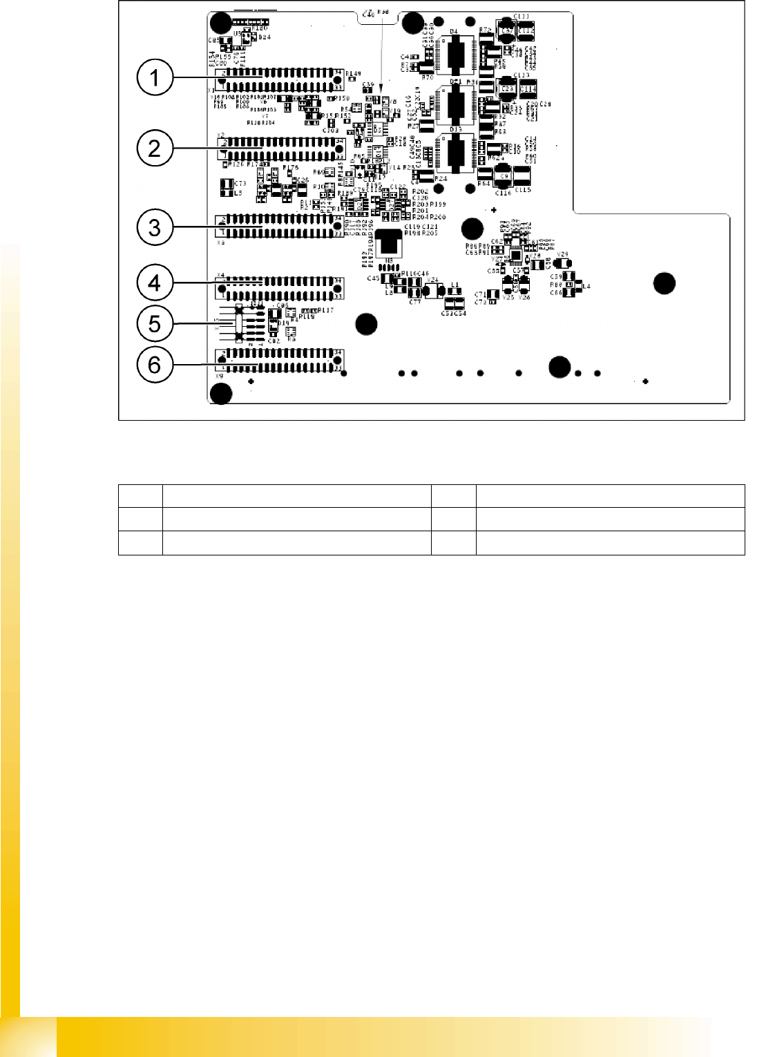
6-9: Gantry head distributor (from below)
Legend
See also:
J 8-Fold DIP Switch of the Gantry Head Distributor (incl. Switch S1) – C&P6/12 [J8-19]
J DIP Switch on Gantry Head Distributor [J6-17]
1 X1 flat ribbon cable 4 X4 not connected
2 X2 flat ribbon cable 5 X15 connector for X-axis track signals
3 X3 flat ribbon cable 6 X9 flat ribbon cable