D-serie LEVEL II.pdf - 第98页
Gantry Settings Anticrash Function for the A364 Axis Cont roller Board S tuden t Guide Advanced Level 2 SIPLACE D Series Gantry EN 05/2007 6-12 6.3.2.5 Anticrash Function

Gantry
Anticrash Function for the A364 Axis Controller Board Settings
Student Guide Advanced Level 2 SIPLACE D Series
EN 05/2007 Gantry
6-11
6.3.2 Anticrash Function for the A364 Axis Controller Board
6.3.2.1 Anticrash Function for the A364
The anticrash function is no longer provided by the anticrash board but instead by the A364 software
(application 1). This means that the proximity switches used to monitor the travel range and the
sensor for monitoring the gantry spacing are no longer required.
Tasks:
– Monitoring the travel range of the X and Y axes
Evaluation of the actual axis position in the direction of the bumper, taking the speed into
account.
– Monitoring the distance for the two Y axes in one placement area
Evaluation of the actual positions of the own and partner gantries during gantry crash monitoring.
– Count error monitoring of gantry axis
Time-based monitoring of the counter pulses received (edge control).
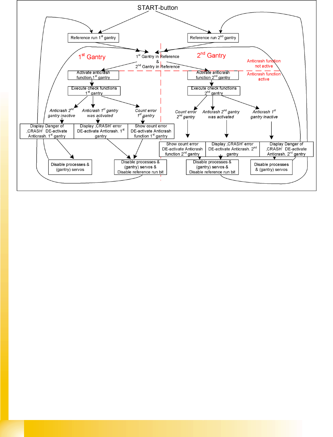
6.3.2.2 Anticrash Monitoring for the A364
The anticrash function is activated after the X/Y axes have been referenced. When first referencing the
gantry axes, the anti-crash monitoring is not active. However, this is not critical, due to the low travel
speed.
After this, the bit is set for the anticrash monitoring function and the actual position for the relevant
partner gantry is continuously communicated via the SPI Bus.
The following information is exchanged between the Y axes:
Actual position and speed of the own gantry
Status information (reference state, anticrash monitoring state ).
Anticrash Monitoring Settings for the A364
6.3.2.3 Error "Gantry Crash"
A “gantry crash” error is established by calculating the position difference and speed difference for both
axes. A gantry crash error is signaled via the axis board and the CAN Bus. The servo is disabled for both
axes and needs to be referenced again.
6.3.2.4 Count Error:
If the axis board detects a "fatal count error", the axis concerned will be disabled and the anticrash
function disabled. The other axis is informed of this in the status information and will also disable the
anticrash function. The disabled axis now needs to be referenced again,
after which the anticrash function will be re-enabled for both axes.
NOTE: No settings
The anti-crash monitoring function is controlled by a rapid software regulator. This means that
there are no longer any settings required for the anti-crash monitoring.
Gantry
Settings Anticrash Function for the A364 Axis Controller Board
Student Guide Advanced Level 2 SIPLACE D Series
Gantry EN 05/2007
6-12
6.3.2.5 Anticrash Function
Gantry
Description of Boards at Gantry Settings
Student Guide Advanced Level 2 SIPLACE D Series
EN 05/2007 Gantry
6-13
6.3.3 Description of Boards at Gantry
The following PCBs at the gantry are in principle identical and independent of the head configuration in
D1, D2 and D4 machines (the D3 has a different board here). The CAN bus terminating resistor is fixed
onto the gantry head distributor.
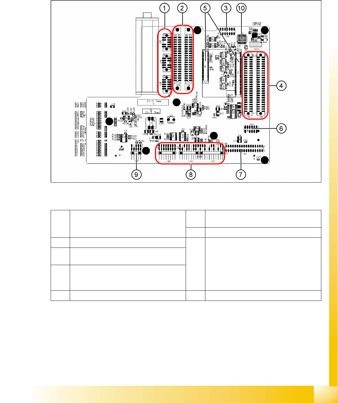
6.3.3.1 Gantry Head Distributor
6-8: Gantry head distributor (from above)
Legend
1 X20 stepping motor reject position
X19 stepping motor pickup/place
X18 stepping motor DP axis, swivel in
6 X24 test connector "digital track signals for X-
axis"
7 X29 Vision board connector
2 X13/X14 flat ribbon cable to C&P head 8 X10 vacuum measurement board connector
X12 motor for DP axis
X16 reference proximity switch (not used)
X17 X-axis end position proximity switch (not
used)
X22 temperature sensor
X21 free (not used)
3 X11 test connector for CAN bus, SPI bus,
RS232
4 X30/X31 flat ribbon cable for D1 P&P head (not
used for D4)
5 X5/X6 connector for 16 bit processor (TQM) 9 X26 connector for component sensor