D-serie LEVEL II.pdf - 第131页
C&P6/12 Placement Head Z-Axis Down Travel Profile - Pickup S tude nt Guide Advanced Level 2 SIPLACE D Series EN 05/2007 C&P6/12 Placement Head 8-5 8.3 T ravel Profile - Pickup 8.3.1 Z-Axis D own 8.3.1.1 D et aile…

C&P6/12 Placement Head
Reference Run (D-Series) Overview
Student Guide Advanced Level 2 SIPLACE D Series
C&P6/12 Placement Head EN 05/2007
8-4
8.2 Reference Run (D-Series)
The placement machine reference run guaranties the correct function for placement in the station SW.
This is where the reference runs for the C&P head and for the gantry are described. A separate chapter
describes the reference run for the P&P module, performed parallel to that for the C&P head.
8.2.1 Overview
The reference run is divided into 4 main steps. Module reference runs for the WPC or for a 2nd
placement head per gantry are not listed at this stage.
1. Conveyor system reference run
This activates the unoccupied (not occupied with a PCB) conveyors.
(in older SW versions, this function can also be performed to conclude the reference run.)
2. Axis reference run
This is divided into:
A.) the head axis reference run and
B.) the gantry axis reference run.
The gantry head axes are started at the same time. As many functions as possible are performed at
the same time.
3. Vacuum reference run
The
A.) vacuum values "open" and "closed" for placement are determined and
B.) all segments in the DP stations are rotated into their 0 degrees positions.
4. Height Reference Run
This function tests the length of the segment nozzles and of the heads in a placement area, on the
top surface of a conveyor side.
These are described and explained in detail below. Machine type or configuration-related extensions or
deviations are explained in separate texts to prevent confusion.
8.2.2 Reference Run Details
NOTE: Reference run details
The reference run details can be found in the AL1 course documents in the chapter Reference
Run.
C&P6/12 Placement Head
Z-Axis Down Travel Profile - Pickup
Student Guide Advanced Level 2 SIPLACE D Series
EN 05/2007 C&P6/12 Placement Head
8-5
8.3 Travel Profile - Pickup
8.3.1 Z-Axis Down
8.3.1.1 Detailed Standard Pickup Procedure: Z-Axis Down
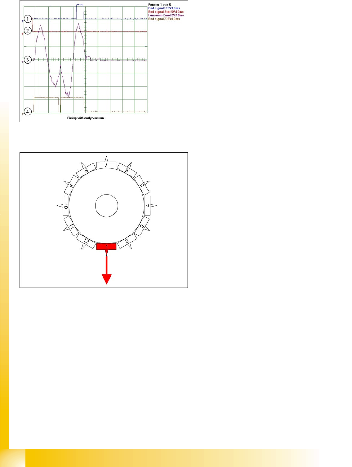
8-4: Star position 0°: detailed pickup procedure: Z-axis down
Start gantry axes to pickup position of next feeder
and communication with changeover table: Start
signal to gantry axes
Start signal X & Y axis to next feeder/this
opens the feeder flap
End position signal for X/Y and star axes:
End position signal for star axis
Enables vacuum query: "segment airtight?"
before pickup
X/Y end position signals available.
Z-axis starts:
Z-axis starts positioning downwards
Light barrier (LB) up switches:
Release signal for function LB down, (after a
waiting period of approx. 3.6 ms, depending
on the DIP switch, special function, currently
not active as a default)
LB down switches:
End position signal for positioning Z-axis down
and valve positioning drive ON for vacuum.
Legend
1. End position signal for Y-axis (position to
feeder pickup position)
2. End position signal for star axis
3. Uncommutated motor current for Z-axis
4. End position signal for Z-axis
Section 1: move down
Section 2: move up
8 ms after the end position signal for the Z-
axis, the system switches over to vacuum and
the Z-axis is restarted and moved upwards.
C&P6/12 Placement Head
Travel Profile - Pickup Z-Axis Down
Student Guide Advanced Level 2 SIPLACE D Series
C&P6/12 Placement Head EN 05/2007
8-6
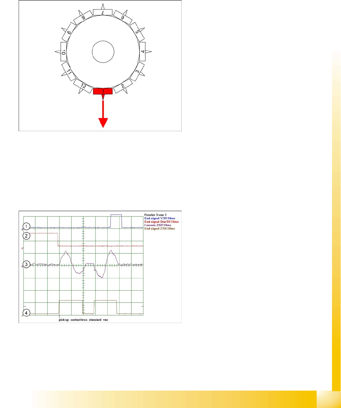
8.3.1.2 Special Mode "Contactless Pickup" Z-Axis Down
Pickup procedure for "contactless pickup":
Start gantry axes to pickup position of feeder and communication with changeover table:
– Start signal to gantry axes
– Signal for next feeder / this opens the feeder flap
End position signal for X/Y and star axes:
– End position signal for star axis
– Enables vacuum query: "segment airtight?" before pickup
– X/Y end position signals available.
Z-axis starts with operating mode "positioning type - absolute" to saved nominal height:
– Positioning of Z-axis down
Light barrier (LB) up switches:
– Release for function LB down (although not needed))
Legend
1. End position signal for X-axis (position to
feeder pickup position)
2. End position signal for star axis
3. Uncommutated motor current for Z-axis
4. End position signal for Z-axis
Section 1: move down
Section 2: move up
In contrast to the previous diagram, a delay of
typically 2 ms occurs for early vacuum.
8-5: Special mode Z-axis down with "early vacuum ON in top position"
In the case of LRU/LRL 503 and SIPLACE Pro,
contactless pickup can only be programmed in the
CS for SR/MC 503 stations and higher.
When the component track, for which contactless
pickup has been programmed, is accessed for the
first time, the following is performed:
The Z-axis is taught the pickup height with
increased force. The Z-axis moves until it
mechanically stops.
This pickup height is then reduced by 1.13 mm
(602) to give the nominal height (path of
segment deceleration and ...) and is saved.
The component used for the teaching
procedure is rejected.