D-serie LEVEL II.pdf - 第89页
Gantry Mechanical Structure Overview S tude nt Guide Advanced Level 2 SIPLACE D Series EN 05/2007 Gantry 6-3 6.1.1.2 Y -Axis Mechanical Structure 6-3: Mechanical axis structure – part 2 - view from below (D4 shown as exa…
Gantry
Overview Mechanical Structure
Student Guide Advanced Level 2 SIPLACE D Series
Gantry EN 05/2007
6-2
6.1.1 Mechanical Structure
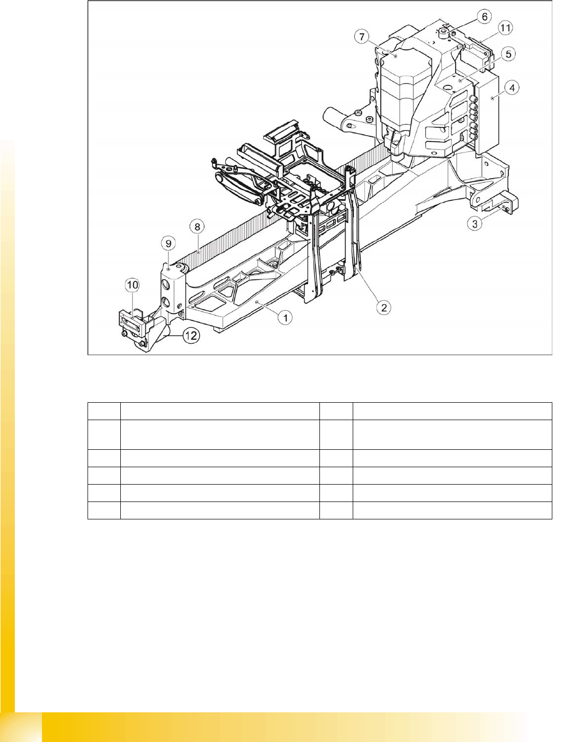
6.1.1.1 X-Axis Mechanical Structure
6-2: Mechanical axis structure – part 1 (D4 shown as example)
Legend
Mechanical Structure
With the help of a toothed belt drive, the rotary movement of the X-axis motor is directly converted into
a lengthwise movement of the placement head, in the X-direction.
The linear guide rails under the X-axis guide the head assembly plate and the placement head along the
X-axis.
The X-motor is cooled by a fan at the Y-axis pickup position and the motor temperature is also monitored
by a sensor.
1 Precision-cast gantry 7 X motor unit
2 Head mount with support for gantry head
distributor board
8 Toothed belt
3 Incremental encoder for Y-axis scale 9 Deflection unit
4 Primary part Y-linear motor 10 Y brake outside
5 Motor bracket X / heat sink (tab) Y motor 11 Y brake inside
6 Thrust bearing 12 Bumper X-axis outside
Gantry
Mechanical Structure Overview
Student Guide Advanced Level 2 SIPLACE D Series
EN 05/2007 Gantry
6-3
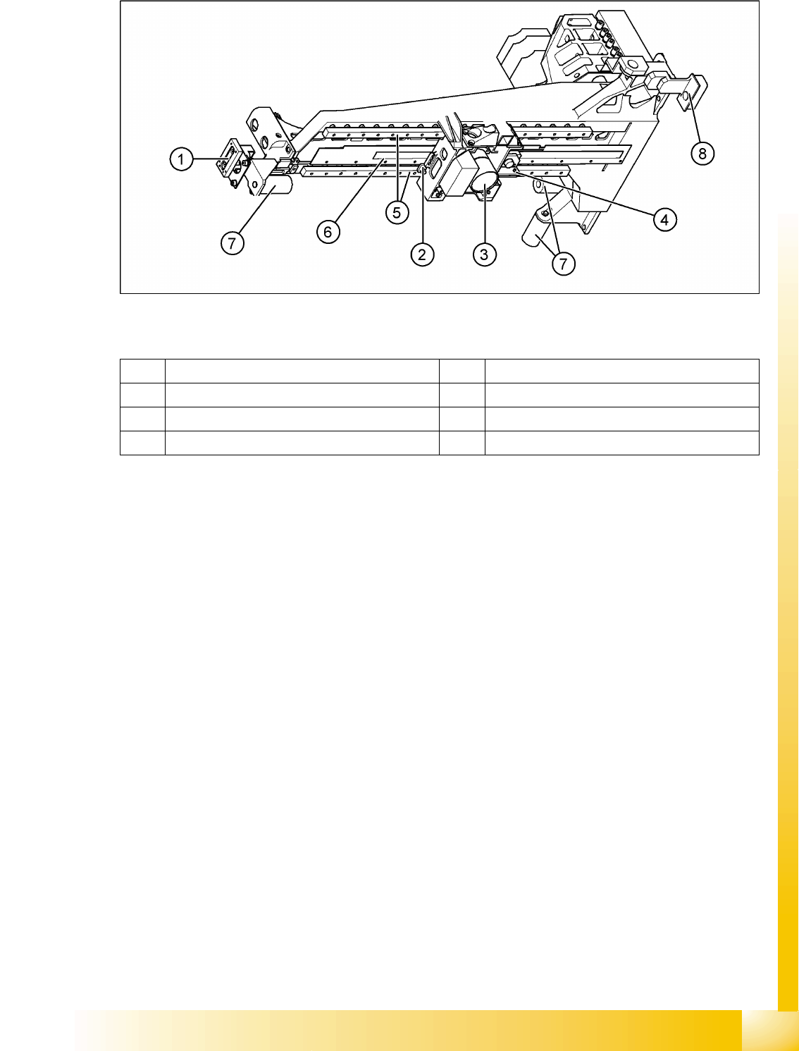
6.1.1.2 Y-Axis Mechanical Structure
6-3: Mechanical axis structure – part 2 - view from below (D4 shown as example)
Legend
Mechanical Structure
A linear motor positions the entire gantry (X-axis, head assembly plate and placement head) in the Y-
axis direction. This linear motor consists of a primary and secondary part. The secondary part consists
of permanent magnets, which are fastened lengthwise (Y direction) to the machine frame.
The primary part consists of inductors (motor windings), which are directly fastened to the gantry, in a
casing.
The drive is cooled by the compressed air supply to the placement head and also has integrated
temperature sensors, which are monitored by the axis controller.
1 Y brake 5 2x linear guide rails, each with a linear bearing
2 X brake 6 X-axis incremental scale
3 Digital PCB camera (shape varies) 7 Elastomeric spring 25x10.5x50
4 X-axis incremental encoder 8 Y-axis incremental encoder
Gantry
Overview Mechanical Structure
Student Guide Advanced Level 2 SIPLACE D Series
Gantry EN 05/2007
6-4
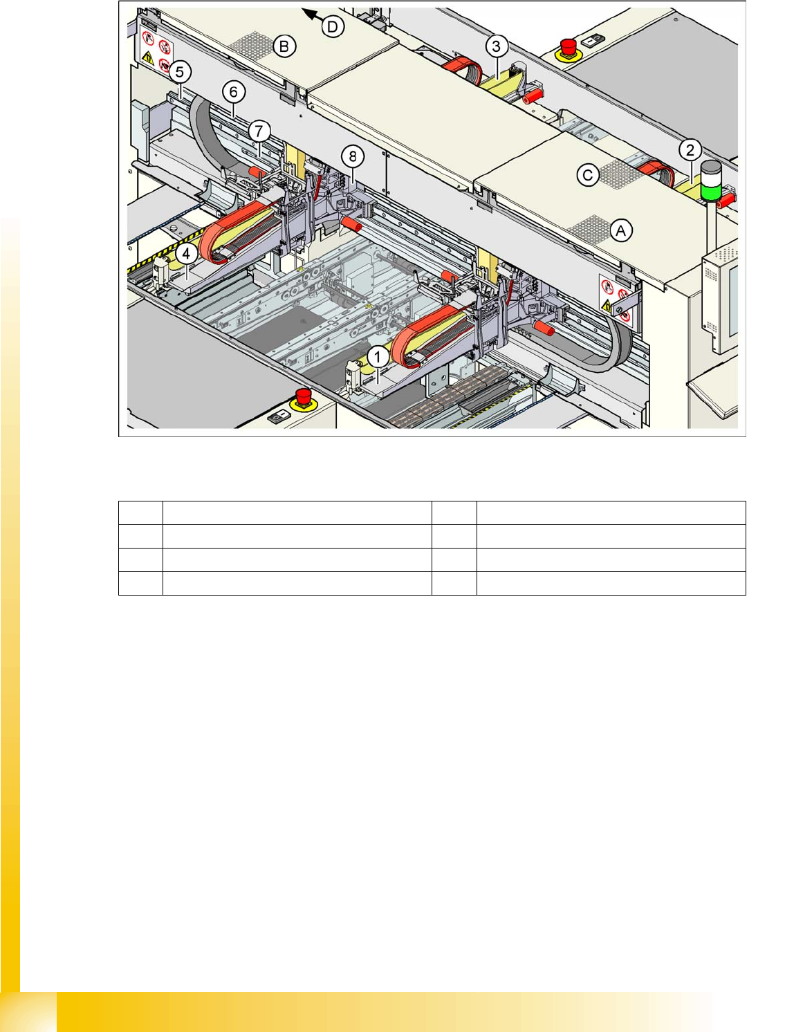
Y-Axis Construction
6-4: Y-Axis Design and Fan Positions (D4)
Legend
Additional X motor cooling is performed at the respective pickup position. The diagram above shows the
following pickup positions:
Pickup position for gantry 1 (A)
Pickup position for gantry 4 (B)
Pickup position for gantry 2 (C)
Pickup position for gantry 3 (D)
Do not cover the fan and service the filter fitted there.
1 Gantry 1 5 Guide system
2 Gantry 2 6 Linear motor secondary part
3 Gantry 3 7 Measuring system
4 Gantry 4 8 Linear motor primary part