D-serie LEVEL II.pdf - 第138页
C&P6/12 Placement Head Travel Profiles - Placement Z-Axis Down S tuden t Guide Advanced Level 2 SIPLACE D Series C&P6/12 Placement Head EN 05/2007 8-12 8.4 T ravel Profiles - Placement 8.4.1 Z-Axis D own 8.4.1.1 …
C&P6/12 Placement Head
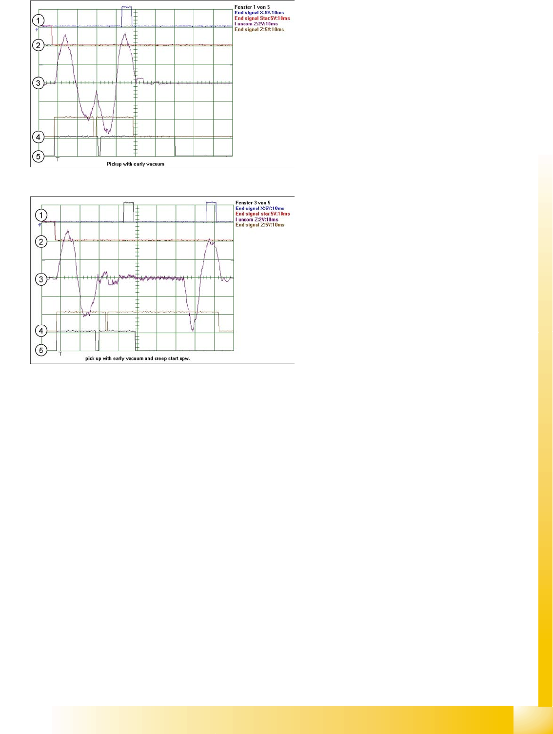
Z-Axis Up Travel Profile - Pickup
Student Guide Advanced Level 2 SIPLACE D Series
EN 05/2007 C&P6/12 Placement Head
8-11
Legend
1. End position signal for X-axis
2. End position signal for star axis
3. Uncommutated current for Z drive
4. End position signal for component pickup with
early vacuum and standard acceleration up
5. End position signal for component pickup with
early vacuum and slow start up
Legend
1. End position signal for X-axis
2. End position signal for star axis
3. Uncommutated current for Z drive
4. End position signal for component pickup with
early vacuum and creep start up
5. End position signal for component pickup with
early vacuum and standard acceleration up
C&P6/12 Placement Head
Travel Profiles - Placement Z-Axis Down
Student Guide Advanced Level 2 SIPLACE D Series
C&P6/12 Placement Head EN 05/2007
8-12
8.4 Travel Profiles - Placement
8.4.1 Z-Axis Down
8.4.1.1 Standard Mode - Placement: Z-Axis Down
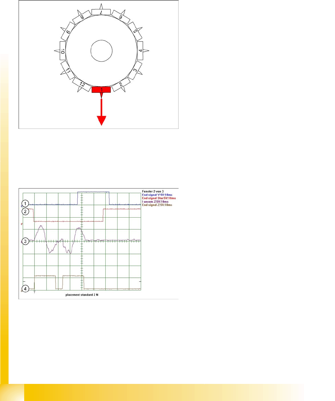
8-9: Detailed component placement procedure: Z-axis down
The placement force is roughly 2.4 N in this
operating mode, with light barrier down on the
C&P12.
End position signal for X/Y and star axes:
All 3 end position signals available
Perform vacuum test "before placement". This
determines whether the component is at the
nozzle.
Z-axis starts:
Positioning of Z-axis downwards
LB up switches:
Electromagnetic valve for air blast ON
Release signal for function LB down
LB down switches:
End position signal for positioning Z-axis
down;
And valve positioning drive pickup/placement
position ON for air blast
Legend
1. End position signal for Y-axis (position to next
placement position)
2. End position signal for star axis
3. Uncommutated motor current for Z-axis
4. End position signal for Z-axis
C&P6/12 Placement Head
Z-Axis Down Travel Profiles - Placement
Student Guide Advanced Level 2 SIPLACE D Series
EN 05/2007 C&P6/12 Placement Head
8-13
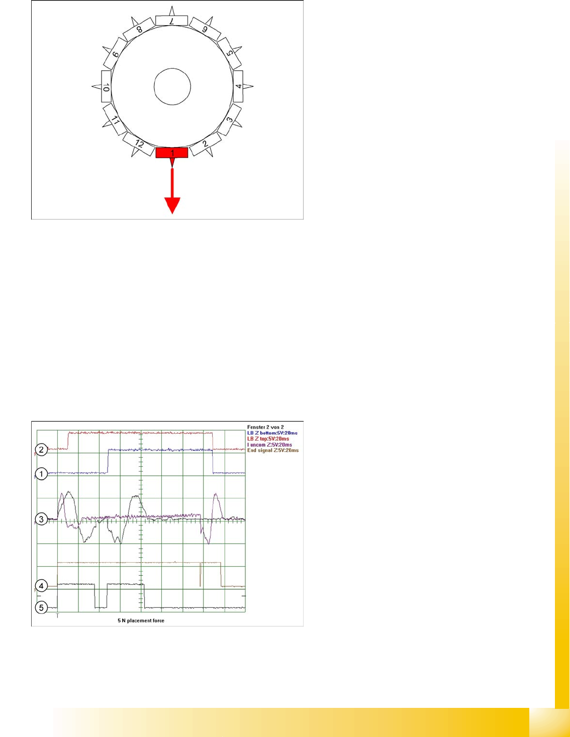
8.4.1.2 Placing with Increased Placement Force: Z-Axis Down
Benefits of Operating Mode "Increased Placement Force"
With this "higher placement force" function, you can:
Reliably set large components and components with large contact surfaces into the soldering paste/
adhesive!
However, this option makes the placement procedure around 10 ms longer than the standard
placement procedure!
8-10: Detailed component placement procedure: Z-axis down
The placement force is 3 -5 N in this operating
mode, with current sensor.
End position signal for X/Y and star axes:
All 3 end position signals available
Perform vacuum test "before placement", to
determine whether the component is at the
nozzle.
Z-axis starts:
Positioning of Z-axis downwards
LB up switches:
Electromagnetic valve for air blast ON
Release signal for function LB down
LB down switches:
And valve positioning drive pickup/placement
position ON for air blast
Current sensor triggers in the servo amplifier:
End position signal for positioning Z-axis
down;
Legend
1. Light barrier bottom position Z-axis
2. Light barrier, Z-axis up
3. Uncommutated motor currents for Z-axis (2
modes)
4. End position signal for high placement force
5N
5. End position signal for standard placement
force 2 N