D-serie LEVEL II.pdf - 第109页
Axis Dynamics Axis Dynamic Basics S tude nt Guide Advanced Level 2 SIPLACE D Series EN 05/2007 Axis Dynamics 7-3 The overswing explained above shows that the waiting time for the overswing check starts at 13 digits befor…
Axis Dynamics
Axis Dynamic Basics
Student Guide Advanced Level 2 SIPLACE D Series
Axis Dynamics EN 05/2007
7-2
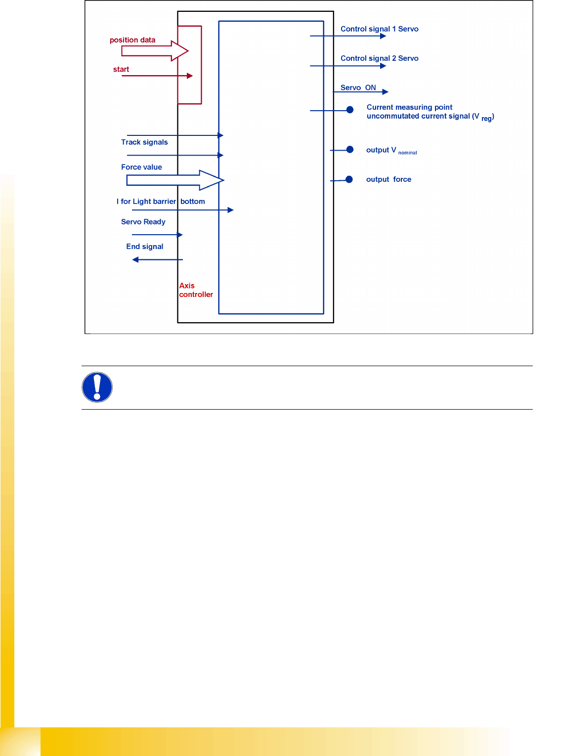
7-1: Digitally controlled axes with A364 for SIPLACE machines
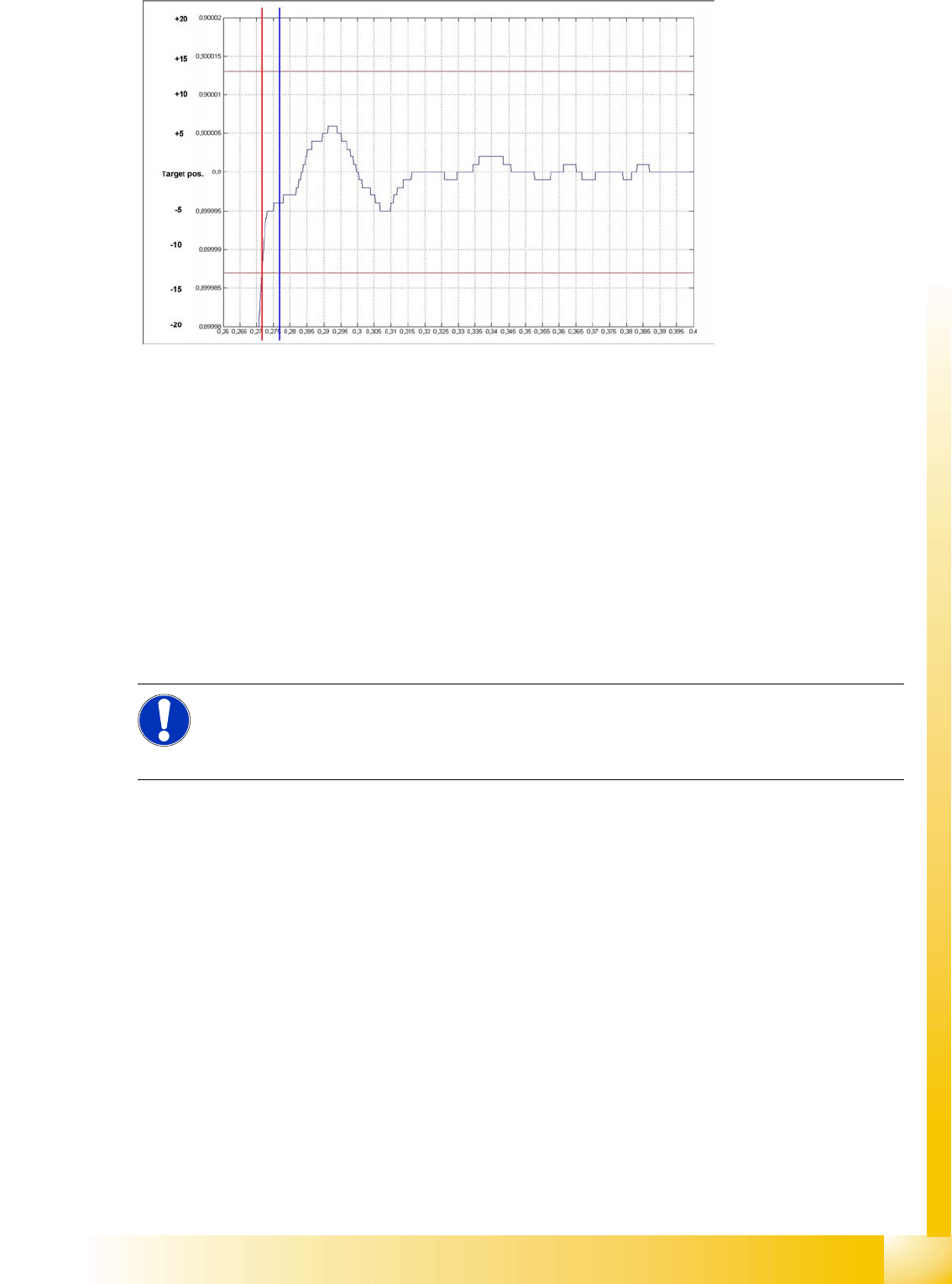
During initial positioning into the target position, the actual equals target position signal triggers an
overshoot count in the SIPLACE Axis Tester, for calculation of the position deviation signal.
If the overshoot is greater than the permitted position deviation (13 digits) for this axis, the end position
signal will be delayed until the deviation has been regulated to remain within the permitted range.
If the axis nears the permitted target position, axis parameters which do not tend to produce overswings
are used. This effective and fast method of regulation seldom produces overswings and has the added
benefit of shorter waiting times for overswing checks (5 ms).
NOTE:
The position deviation signal shows the positioning quality of an axis movement in position.
Axis Dynamics
Axis Dynamic Basics
Student Guide Advanced Level 2 SIPLACE D Series
EN 05/2007 Axis Dynamics
7-3
The overswing explained above shows that the waiting time for the overswing check starts at 13 digits
before the target area and that the end position signal is set at 5 ms after this.
The movements of approx. 6 µm which then occur can then be ignored. These do not affect the machine
or the placement process.
For assessment of the axis dynamics by a service technician, the system generates an uncommutated
current nominal signal from all motor current nominal signals. This informs you about the mechanical
friction in the axis system. It can be measured on the adapter board of the axis controller or at the Vreg
output of the SIPLACE axis tester (SAT).
The uncommutated target current signal is an envelope signal for the 2 visible motor current nominal
signals from the axis controller. The missing 3rd motor current signal is calculated at the Servo board.
The known V nominal (V-target) speed signal and the force signal have been replaced by the motor
current nominal signals for DC or AC drives.
NOTE:
These motor current signals can be measured at the V nominal and the Force output of the
axis tester. The same signals are measured at the two topmost test points of the servo amplifier
board, as Inom. U’ and Inom. W signals.
Axis Dynamics
Axis Dynamic Basics
Student Guide Advanced Level 2 SIPLACE D Series
Axis Dynamics EN 05/2007
7-4
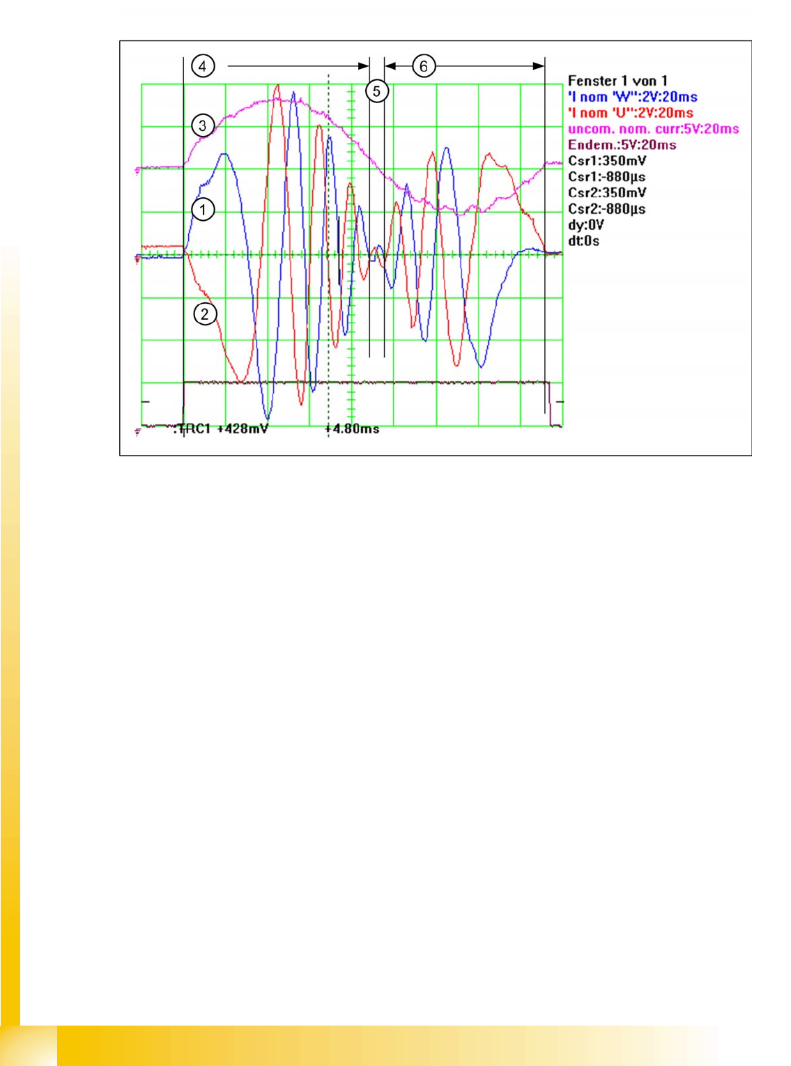
7-2: The uncommutated motor current nominal signal (3) and the motor current signals (1) (2) of an AC Motor
The acceleration section can be recognized in the motor current nominal signal of the AC motor (4), due
to the high amplitudes needed to supply the axis mechanics with sufficient force. The frequency of this
signal section is low, due to the low speed. The amplitude becomes lower and lower because the
necessary motor force is reduced with increasing speed.
The frequency becomes higher as the speed increases, up to a maximum frequency for maximum axis
speed (2).
In the deceleration section, the amplitude increases again, to reduce the speed of the axis mechanics.
The frequency is reduced to a lower value, thereby also reducing the speed of the axis (3). Finally, the
axis is moved into the correct target position, with overshoot control.
So there is nothing to adjust all this axes have a dynamic behavior. Each axis has friction to be
overcome. The higher the friction is, the higher the amplitudes will be at acceleration and constant
speed. The higher motor force at acceleration and constant speed can be detected at the uncommutated
motor current nominal signal. Higher friction reduces the required motor force during the deceleration
section, so that the amplitude is smaller for the uncommutated motor current nominal signal.