D-serie LEVEL II.pdf - 第161页
Component Handling Overview of Pneumatic Cutter with Empty Tape Duct Pneumatic Ta pe Cutter S tude nt Guide Advanced Level 2 SIPLACE D Series EN 05/2007 Component Handl ing 9-1 1 9.4 Pneumatic T ape Cutter 9.4.1 Overview…
Component Handling
Optional Extension on the COT Fixtures for S-Feeders
Student Guide Advanced Level 2 SIPLACE D Series
Component Handling EN 05/2007
9-10
9.3.4 Fixtures for S-Feeders
9.3.5 Additional Communication unit for splice detection
9.3.6 Waffle Pack Changer (WPC)
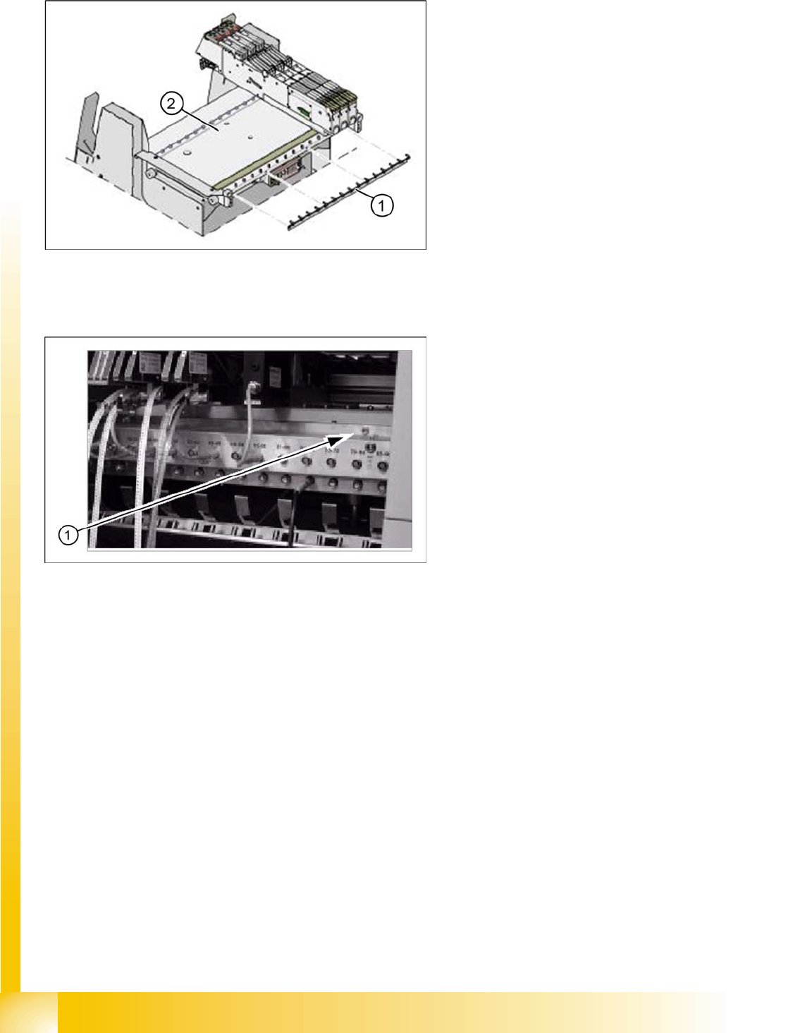
Perform the following steps to fit a WPC4 into a D1 machine:
X Remove the changeover table in location 1.
X Remove the empty-tape duct assembly.
X Remove the waste slide.
X Remove the changeover table stopper.
X Fit the fixed changeover table WPC4 and screw tight.
X Fit the empty-tape duct for 5 feeder locations.
X Insert the WPC, lower and align.
9-6: Feeder fixtures (HF shown as example)
Legend
1. Feeder fixtures
2. Changeover Table
The Feeder-Fixing is an additional mechanical
safety precaution. It prevents accidental
movement of the feeder on the changeover table.
It excludes a head crash risk with a wrong
positioned feeder. The feeder-fixation is mounted
on the front side of the changeover table. The
claws fix the feeder feet. A feeder clamp can be
installed for each of the component trolleys.
9-7: Additional Communication unit for splice detection
An additional communication unit for the option
Traceability with splice detection is necessary.
The splice sensors on the communication unit
inform the station software when a new
component lot (reel) is spliced on. This sets the
new fill level for this component automatically.
Legend
1. The additional communication unit is screwed
into place, together with the changeover table
communication unit.
Component Handling
Overview of Pneumatic Cutter with Empty Tape Duct Pneumatic Tape Cutter
Student Guide Advanced Level 2 SIPLACE D Series
EN 05/2007 Component Handling
9-11
9.4 Pneumatic Tape Cutter
9.4.1 Overview of Pneumatic Cutter with Empty Tape Duct
The pneumatic cutter is fixed to the machine frame with four screws and forms a unit with the empty tape
duct. It separates plastic, aluminum and paper tapes up to a maximum pocket depth of 25 mm. The tape
clippings fall down the waste slide, into the waste tape container of the component trolley.
The empty tape duct is designed to cover the cutting edges of the cutter (to avoid risk of injury), to guide
the empty component tapes to the cutter, to integrate the component reject container and accommodate
the C&P12 nozzle changer.
NOTE:
The D4 machine is used as an example to describe the pneumatic cutter.
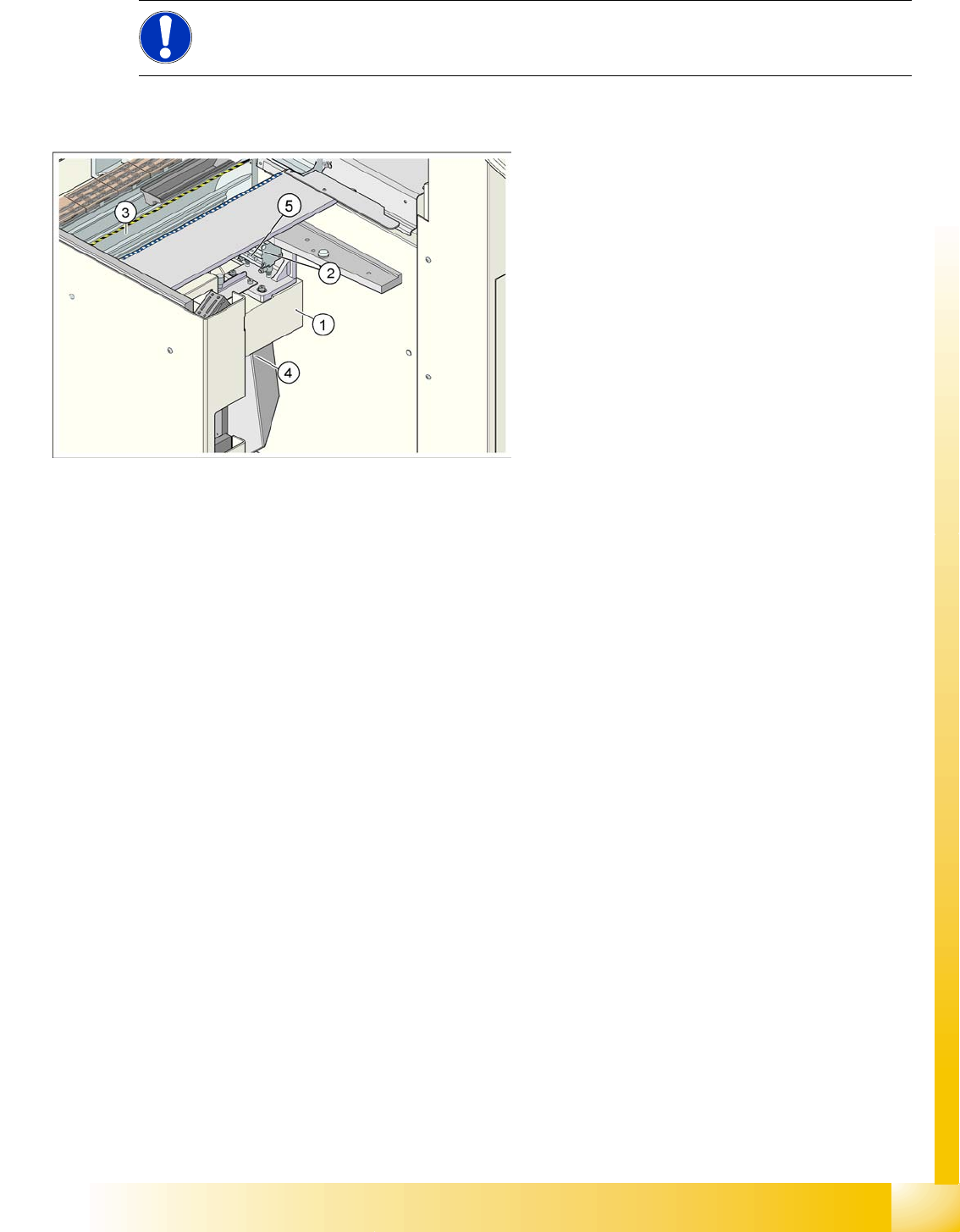
9-8: Complete docking unit
Legend
1. Cross bar
2. Tape cutter
3. Empty Tape Duct
4. Waste slide
5. Proximity switch
Component Handling
Pneumatic Tape Cutter Structure and Function of the Pneumatic Tape Cutter
Student Guide Advanced Level 2 SIPLACE D Series
Component Handling EN 05/2007
9-12
9.4.2 Structure and Function of the Pneumatic Tape Cutter
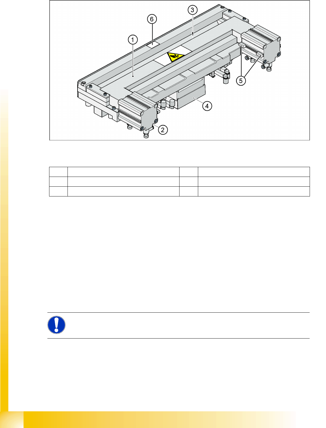
9-9: Pneumatic tape cutter
Legend
The empty tape duct guides the empty tapes through the opening (3) in the cutter.
The cutter is based on a horizontal frame (1) with a fixed cutting edge and a flexible blade, which is
moved by two short-stroke cylinders (2). At each forwards movement, the device cuts off the tape..
The proximity switch (5) signals the position of the short-stroke cylinder pistons and therefore of the
cutter blade. The control electronics (4) (under the cutter) register, for example, any components in the
tape which have not been cut. Cutting is only performed during the placement procedure. For operational
safety reasons, the tape cutter is integrated into the emergency stop circuit.
The tape cutter is activated when the gantry is moving to the placement position. Alternating one of the
cylinders start to front position. Once the first cylinder reaches the front position, the second cylinder is
started. Both signals ’blade in front position’ trigger control unit to withdraw both cylinders at the same
time.
1 Horizontal frame 4 Electronic control unit
2 Pneumatic cylinder 5 Proximity switch
3 Slot for empty tape 6 Fixed blade
NOTE:
The cutter can be removed within about 15 minutes for service purposes. For detailed
information about dismantling, refer to the service manual.