D-serie LEVEL II.pdf - 第94页
Gantry Gantry Settings Pneumatic Connections on the Gantry S tuden t Guide Advanced Level 2 SIPLACE D Series Gantry EN 05/2007 6-8 6.2 Gantry Settings Assembly Tools & equipment * Setting type Comments See also X-dri…
Gantry
Pneumatic Connections on the Gantry Overview
Student Guide Advanced Level 2 SIPLACE D Series
EN 05/2007 Gantry
6-7
6.1.3 Pneumatic Connections on the Gantry
The placement head is supplied with 4.5 bar compressed air from the pneumatic unit. The 7-fold
pneumatic hose is also used to cool the Y-axis motor. The X-axis motor is cooled by the traverse fan.
Y-axis distributor
board
Gantry
distributor
Gantry interface Gantry distributor
End position
proximity switch
None
Light barrier for
anti-crash
monitoring
Not any more Never needed
Anti-Crash Board Not any more
NOTE:
eSW axis controller
All zero pulses for the gantry axes are checked to see whether 50,000 count pulses occur or
whether a whole number multiple of this occurs!!
An overshoot check for gantry axis positioning is no longer required. The continual calculation
of the axis positioning, based on the axis track signals, gives optimal positioning, even in the
case of mechanical defects.
Travel range: axis controller determines hardware position at stopper; 2 mm before; travel range
– software position – 0.5 (X) 1.5 mm (Y) before that - limited.
Assembly D4 D3 D2 D1 D1 single head
Overall gantry design
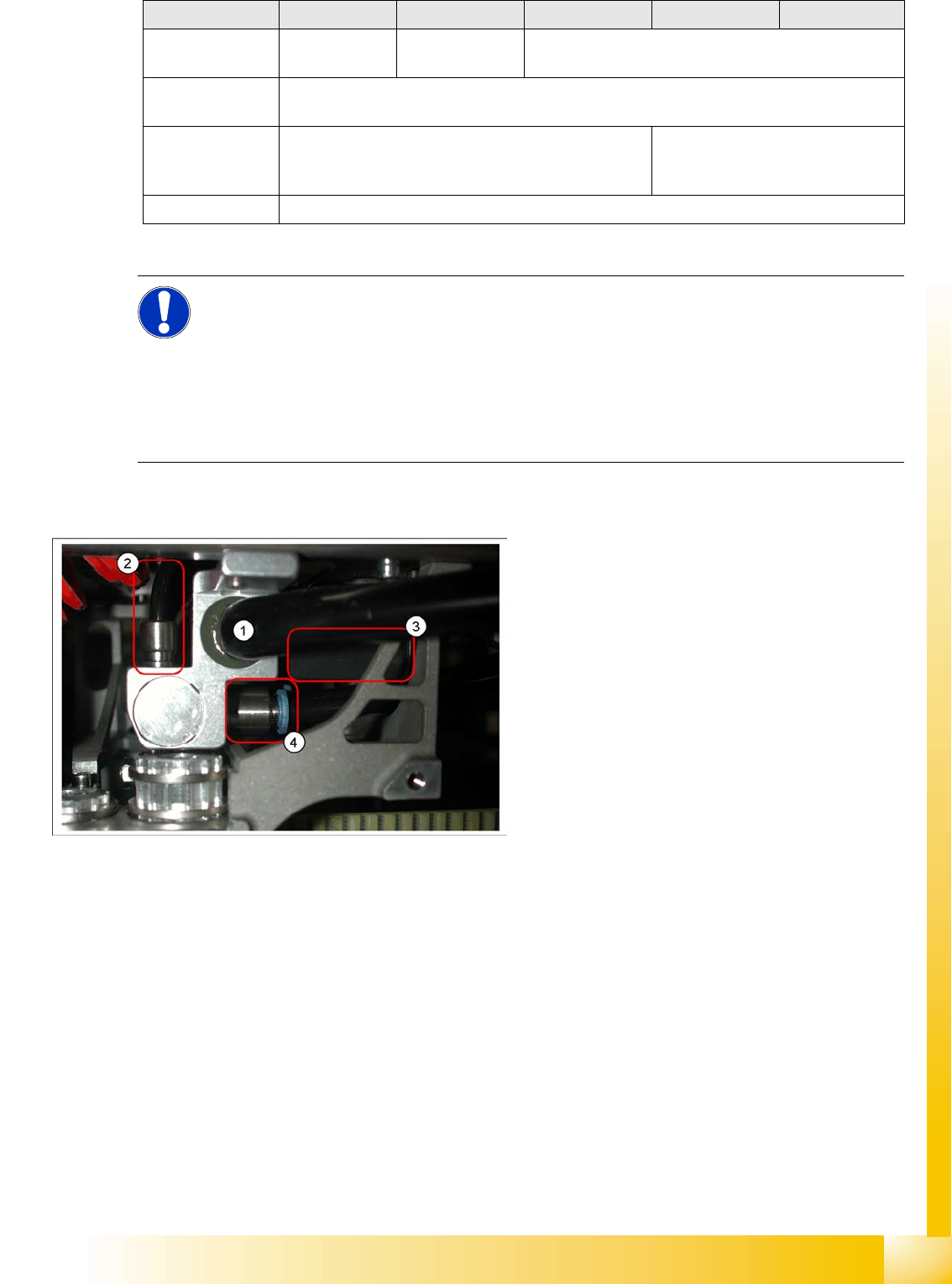
6-5: Pneumatic distributor under the gantry head distributor
Legend
1. Input: Exhaust Venturi nozzle pneumatic hose
(PK12)
2. Input: 7-fold pneumatic hose (PK 5)
3. Silencer for exhaust (indicated in the diagram)
4. Compressed air outlet for pickup/placement
circuit and holding circuit
D1/2: to T distributor C&P/P&P head
D4: to C&P head

Gantry
Gantry Settings Pneumatic Connections on the Gantry
Student Guide Advanced Level 2 SIPLACE D Series
Gantry EN 05/2007
6-8
6.2 Gantry Settings
Assembly Tools &
equipment *
Setting type Comments See also
X-drive
X-motor D1/2 Belt tension
measuring
device
X belt is set at tensioning key to 44 +/-1 Hz
/ axis dynamics
D4 / D2/D1
measure at front
belt if the head is at
far left, against X
motor.
SA
X belt D1/2 Belt tension
measuring
device
X belt is set at tensioning key to 44 +/-1 Hz
/ axis dynamics
X deflection unit
D1/2
Belt tension
measuring
device
X belt is set at tensioning key to 44 +/-1 Hz
/ axis dynamics
X-motor D4 Belt tension
measuring
device
X belt is set at tensioning key to 53 +1/-3
Hz / axis dynamics
SA
X belt D4 Belt tension
measuring
device
X belt is set at tensioning key to 53 +1/-3
Hz / axis dynamics
X deflection unit
D4
Belt tension
measuring
device
X belt is set at tensioning key to 53 +1/-3
Hz / axis dynamics
X brake Screw in screw as far as possible, with
defined spring tension.
X drive magnets
(secondary part)
Glued to CFK gantry – not individually
replaceable
D3 only
X-axis
incremental
encoder
0.4 mm foil Align encoder to scale & with 0.4 mm
space to scale / axis function – dynamics?
Align to count track -
fiducials on encoder
X incremental
scale
0.4 mm space to scale / axis function –
check dynamics.
Reserved for
Siemens Service,
for D2/1 D3 - glue in
place / for D4 screw
in place
Y drive Linear motor
Y drive magnets
(secondary part)
0.8 mm space below and between the
boards
D-series
Y brakes Pretension due to gantry suspension D-series
Y-axis
incremental
encoder
0.4 mm foil Align encoder to scale & with 0.4 mm
space to scale / axis function – dynamics?
Align to count track -
fiducials on encoder
Y incremental
scale
Align along the Y guide rail with special
tool/ 0.4 mm space to scale / axis function
– check dynamics in continuous run.
Reserved for
Siemens Service -
different gauges to
be glued in place,
for D4/D3/D2/1
Gantry head
distributor
DIP switch as specified for the respective
gantry arrangement
'Head interface’ Currently --
-
Settings/checks
Gantry
Fitting the Incremental Scale Settings
Student Guide Advanced Level 2 SIPLACE D Series
EN 05/2007 Gantry
6-9
*
Equipment in addition to standard manual tools
6.2.1 Fitting the Incremental Scale
6.3 Settings
For detailed information about the assemblies and their settings, refer to the service guide for the
respective machine.
6.3.1 Travel Ranges and Speed Monitoring at the D4 (A364)
The travel range of the X- and Y-axes is determined automatically with the SITEST program.
This means that, during travel range calibration, the axis concerned moves stepwise towards the
minimum or maximum position, until the set target value is no longer reached by the axis. It is then
assumed that the hardware limit switch (bumper) has been reached. After a time window of approx.
10 ms, the greatest actual value achieved is taken to calculate the travel range.
To guarantee an appropriate safety distance before the hardware end position is reached, a certain
distance is deducted from the set travel range and is defined as the software end position for the
axis.This enables the axis to brake in time, even when errors occur.
Head distributor ––– 'Gantry interface’ Currently --
-
Trailing cable
distributor
––– Trailing cable
interface
Currently --
-
Axis dynamics
X-motor
(primary part)
Axis dynamics D3 (5ms faster than
with 602)
Y-motor Axis dynamics D3 (5ms faster than
with 602)
Y drive magnets Axis dynamics? D3
Assembly Tools &
equipment *
Setting type Comments See also
Settings/checks
NOTE: X incremental scale
X The X incremental scale on the D4 is glued to a metal strip, which can be unscrewed.
X The X incremental scale on the D3 is to be glued onto an aluminum strip, along the stopper
edge. Before stripping off the scale, mark where it starts on the aluminum strip.
X The D1/2 scale is glued to the fixed base plate of the gantry.