D-serie LEVEL II.pdf - 第113页
Axis Dynamics Track Signals and Zero Pulse Signal Position Measuring System S tude nt Guide Advanced Level 2 SIPLACE D Series EN 05/2007 Axis Dynamics 7-7 The posit ion is deter mined by a position co unter on the axis c…
Axis Dynamics
Position Measuring System Track Signals and Zero Pulse Signal
Student Guide Advanced Level 2 SIPLACE D Series
Axis Dynamics EN 05/2007
7-6
7.2 Position Measuring System
7.2.1 Track Signals and Zero Pulse Signal
Our Axes systems consists of the following parts.
Axis controller for main board
Servo amplifier
Motor
Position measuring system with incremental scale and encoder
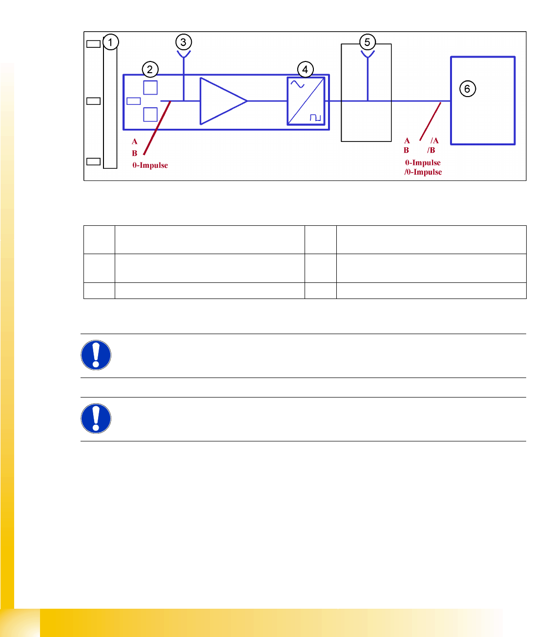
7-4: Principle circuit for position measuring systems
Legend
The axis control system with closed position control loop determines the axis position directly, based
on the mechanical movement of the axis. The position measurement system generates analog track and
zero pulse signals during movement over the incremental scale. An amplifier, a multiplier switch and a
signal former are integrated into the encoder housing. A test connector for digital signals is either
installed on the next interface board or the digital signals are measured at track A/B and the zero pulse
output of the SIPLACE axis tester. The track signals are the only feedback loops in all the axis control
systems of the SIPLACE machine. This means that each track recognition error affects the axis control
system. The gantry axes immediately stop at a fault; the head axes finish the positioning to target before
showing a track signal error.
1 Incremental scale with zero pulses 4 Electronic signal multiplication and signal
digitalization
2 Incremental encoder for track A/B and zero
pulse signals (O pulse.)
5 Test output digital signals
3 Analog signal output and amplifier 6 Axis controller
NOTE:
The incremental encoders in 1 field lens technology have the same general construction. The
transmitter and receiver of A/B count signals are located behind a common lens window.
NOTE:
This new incremental encoder supplies track signal output amplitudes of between 1.8 and
3.6 Vss, compared to the old incremental encoder which achieved a maximum value of 2.5 Vss.
Axis Dynamics
Track Signals and Zero Pulse Signal Position Measuring System
Student Guide Advanced Level 2 SIPLACE D Series
EN 05/2007 Axis Dynamics
7-7
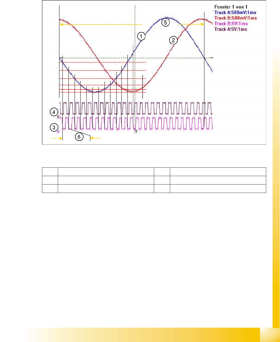
The position is determined by a position counter on the axis controller. The moving direction of the axis
is determined by the phase shift of the track signals An advanced track A signal indicates movement to
the right, while an advanced track B signal indicates movement to the left. To make the encoder system
robust for the high resolution we multiply the frequency of the analog signal and create a high resolution
digital measuring system.
7-5: Principle signal multiplication at analog Track signals of a gantry axis
Legend
The signal multiplication can be realized as a Schmitt trigger action. During comparison of the analog
and digital axis signals, a signal multiplication of 25 (see diagram above), 10 or just 1 can be recognized.
The track signals of the C&P head axes can only be measured as digital signals i.e. The analog signals
are directly converted in the encoder housing, without provision of a test connection for the analog
signals.
1 Analog track A signal incremental encoder 4 Digital track B signal at Test connector
2 Analog track B signal Incremental encoder 5 Period time of analog track signal
3 Digital track A signal at Test connector 6 Period time of digital track signal
Axis Dynamics
Position Measuring System Zero Pulse at the Track Signal Encoder
Student Guide Advanced Level 2 SIPLACE D Series
Axis Dynamics EN 05/2007
7-8
7.2.2 Zero Pulse at the Track Signal Encoder
Each incremental encoder system needs initializing. This means a reference run is executed for each
axis. At the reference run the system searches for a certain position - the signal for this is the Zero pulse.
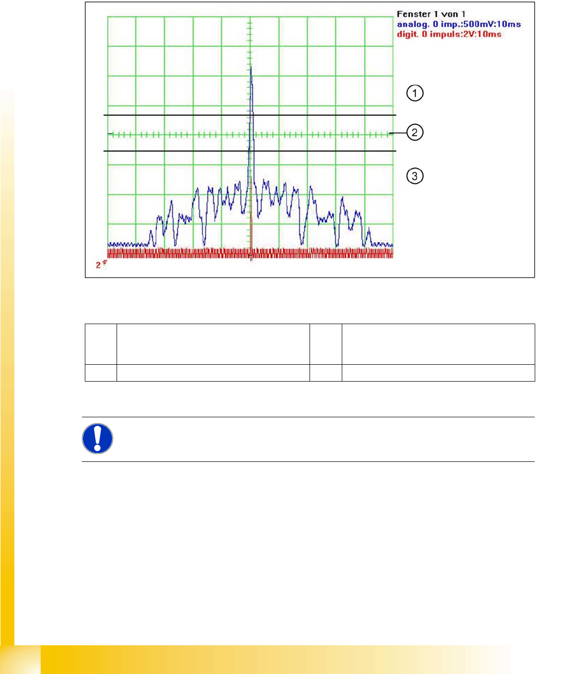
The Zero pulse is an analog signal and a ’Schmitt Trigger’ circuit digitizes it.
(Measurement of analog signal by setting the
zero line
at the center of the screen)
7-6: Analog and digital zero pulse signal (zero line set at screen center)
Legend
At around 2.5 V the Schmitt trigger circuit issues a brief, high pulse: the zero pulse for the position
measurement system. If the encoder has been installed too near to the incremental scale, one of the
auxiliary pulses could exceed the Schmitt trigger threshold and be mistakenly recognized as the zero
pulse. This would mean that the zero pulse would be recognized in the wrong position on the incremental
scale. This would then lead to a placement offset on the SIPLACE machine. The digital zero pulse is
measured on the gantry head distributor, with a probe at Pin 8 of the test connector. The inverted zero
pulse can be measured at the zero pulse output on the axis test box (or the SIPLACE AxisTester SAT).
The A364 axis controller considers all the zero pulses on the track scale i.e. even those which are
repeated after 50 mm.
1 The analog zero pulse needs to be 0.3 V higher
than the trigger threshold for the digital zero
pulse.
3 Glitches (signal noise) should not override the
limit 0,3 V less than Trigger threshold!
2 Schmitt trigger threshold
NOTE:
The A364 axis controller detects each X/Y scale zero pulse and checks the count values for
errors.