D-serie LEVEL II.pdf - 第207页
SITEST Travel Range Calibration Basics S tude nt Guide Advanced Level 2 SIPLACE D Series EN 05/2007 SITEST 12-7 12.2.4 T ravel Range 12.2.4.1 Position of Calibration T ool Calibrate the X and Y pick up position of the …

SITEST
Calibration Basics Machine Zero Point
Student Guide Advanced Level 2 SIPLACE D Series
SITEST EN 05/2007
12-6
12.2 Calibration Basics
12.2.1 Machine Zero Point
The center of the PCB camera is used by the gantry as a reference point. All X/Y axis positions then
relate to this camera center point.
The reference point for the machine zero point is a drilling next to the calibration tool rest.
As soon as the PCB camera of the relevant gantry is positioned over the center of this drilling and
the drilling center has been optically centered, the gantry position will be set exactly to the following
values:
MA zero point_x_PG1 739500 / MA zero point_y_PG1 662400.
MA zero point_x_PG2 1303500 / MA zero point_y_PG2 1248400
(PG means gantry group)
12.2.2 PCB Camera
The pixel size of the CCDx sensor is determined (in µm)
The calculation takes into account the Ax/Bx/Cx/Ay/ByCy calibration values. The data is saved at
camera.xml
in nm (i.e. 1 pixel 11.7x11.7 µm)
The pixel size is:
approx. 11770 nm for the standard camera SST 34,
approx. 11770 nm for the multicolor PCB camera SST 24,
The camera center is determined.
This camera center point is now the reference point for all machine positions!
The angle of the CCD sensor in the PCB camera to the machine coordinate system. The value is
saved as
Position_angel
in the PCB camera data block, at
camera.xml
.
12.2.3 Position of Calibration Tool
Calibrate the X and Y pick up position of the calibration tool.
SITEST
Travel Range Calibration Basics
Student Guide Advanced Level 2 SIPLACE D Series
EN 05/2007 SITEST
12-7
12.2.4 Travel Range
12.2.4.1 Position of Calibration Tool
Calibrate the X and Y pick up position of the calibration tool.
12.2.5 Component Camera
The Pixel size of the CCD sensors of the camera is determined in µm. Measured and calculated with
Ax/Bx/Cx/Ay/ByCy calibration values. Saved in
camera.xml
as: XU_Pixel / YU_Pixel in nm
The pixel size is:
approx. 49700 nm for component camera SST 28 (for 12-segment head)
approx. 26760 nm for component camera SST 29 (for 6-segment head/12-segment head option)
approx. 17220 nm for component camera SST 23 (for 20-segment head)
The camera center is determined.
The Mounting angle of the CCD-chip in the camera to the turning level of the placement star is
measured. The value is saved as Kamera_winkel (camera_angle) in the data block of the component
camera, in the
camera.xml
.
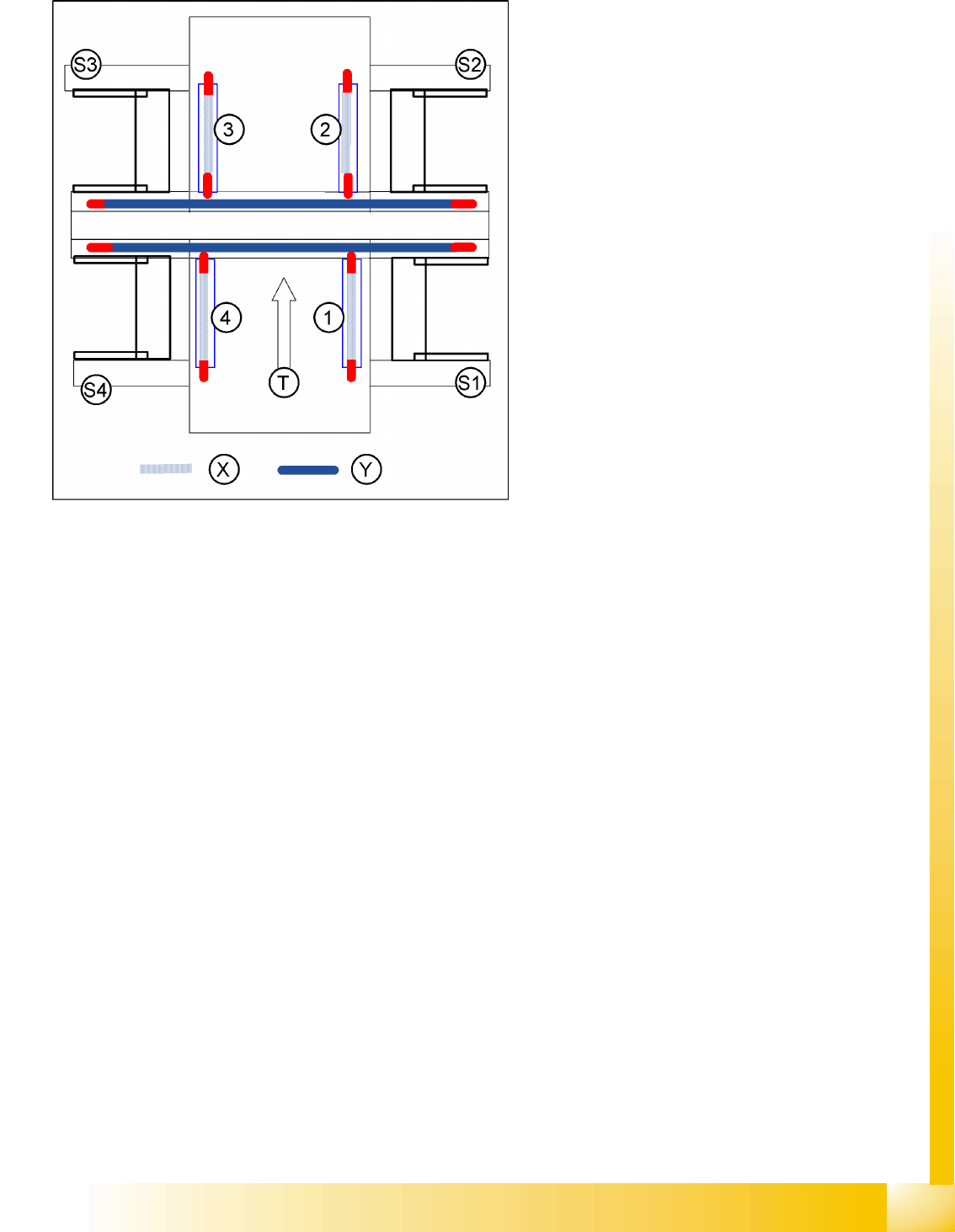
X gantry axis:
The X gantry axis moves to the zero pulse, to
calibrate the travel range and then moves on
to the HW end stoppers (limit switch). The
respective gantry axis position is recorded
there.
The maximum hardware travel range is set 1.5
mm before the bumper. The software travel
range value is 0.5 mm before that.
Y gantry axis:
The Y gantry axis moves to the zero pulse, to
calibrate the travel range and then moves on
to the outer HW end stoppers on the left or
right (limit switch). The respective gantry axis
position is recorded there.
The maximum hardware travel range is set 1.5
mm before this position. The software travel
range value is 1.5 mm before that.
In the case of the Y axes, only the outer HW
end stoppers are approached in each case.
The other end position of the travel path is
calculated. This gives a travel range distance
to the other gantry of about 35 mm.
Legend
1-4:Gantry 1-4
S1 - S4:Sector 1-4
X:Travel range X
Y:Travel range Y
T:Transport direction
SITEST
Calibration Basics Component Camera
Student Guide Advanced Level 2 SIPLACE D Series
SITEST EN 05/2007
12-8
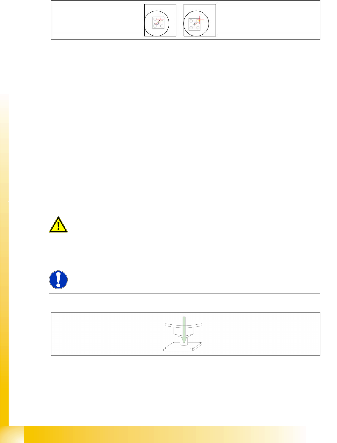
Sequence segment offset top (I):
12-1: Principle picture of a calibration tool in the camera in 0° (left); in 180°(right).
PCB Camera - Component Camera Offset:
During measurement of the segment offset up (I), the calibration of the PCB camera -> component
camera offset is performed with segment 1:
The distance in X- and Y- direction of the camera centers is determined in µm.
The top segment offset (I) is compared to a calculated average value. (the segment offset I of
segment 1 is therefore no longer 0.)
Segment 1 is the reference point for calculation of the offset (I and II).
This distance is saved in REAL.MA at ‘Kopfoffsets’ at Kopf 1 Kopfoffset_X /..Y. The segment offset
down (II) for segment 1 is 0 (see below).
The segment offsets for the remaining 11 segments are saved in the PIP_OFF.MA file (as deviation
to segment 1).
Deviation in the X and Y direction of the rotary axis for the remaining segments, compared to
segment 1 (in µm).
Measurement is performed at 0° and 180° or 90° and 270° in each case. The center of the segment
is then determined from these 0/180° or 90/270° values.
The values for the segment offset are saved in the PIP_OFF.MA file.
Sequence segment offset bottom (II):
12-2: Sequence at one nozzle:
After the segment offset up (I) calibration step has been performed, the calibration procedure for the
segment offset down (II) begins for C&P DLM 3:
Is the calibration tool picked with a Nozzle under 0 degree; optically centered and placed with the
PCB-camera is the exact placement position determined (in µm).
ATTENTION:
For the segment offset I (top), the standard deviation value should not exceed 600 µm. The
difference between the segments must not exceed +/- 150 µm.
Segment offset II (down) absolute threshold +/- 150 µm and difference in values max. +/-
150 µm.
NOTE:
The segment offset II (bottom), from the first segment is always 0 that is the reference value to
the other segments.