D-serie LEVEL II.pdf - 第87页
Gantry Overview S tude nt Guide Advanced Level 2 SIPLACE D Series EN 05/2007 Gantry 6-1 6G a n t r y 6.1 Overview The SIPLACE D-s eries gantri es consists of an X an d Y axis each. The Y-axis is powered by a linear motor…

Energy and Compressed Air Supply
Room for Your Sketches and Notes Bulk Case System
Student Guide Advanced Level 2 SIPLACE D Series
Energy and Compressed Air Supply EN 05/2007
5-20
Gantry
Overview
Student Guide Advanced Level 2 SIPLACE D Series
EN 05/2007 Gantry
6-1
6Gantry
6.1 Overview
The SIPLACE D-series gantries consists of an X and Y axis each. The Y-axis is powered by a linear
motor with integrated temperature sensor. The X-axis is powered by a 3-phase servo motor, which is
fitted with an integrated temperature sensor and which is driven by a belt. When viewed in the direction
of transport, the Y motors move from left to right in a positive counting direction and the X motors move
from the input conveyor to the output conveyor, in a positive counting direction. The placement heads
are mounted on the head plates of the respective X axes.
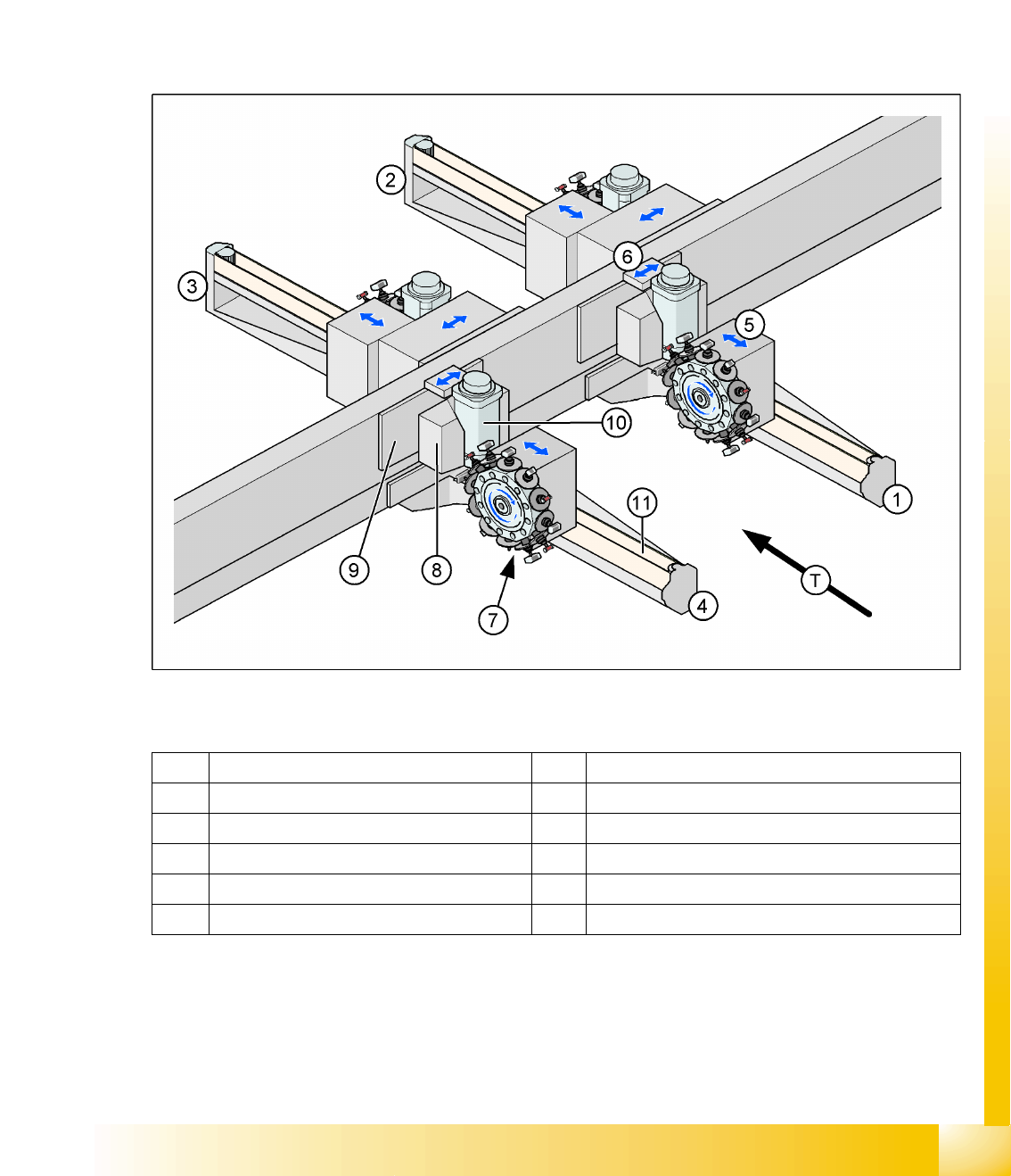
6-1: Position of D4 machine gantries
Legend
1 Gantry 1 in placement area 1 7 PCB camera under the X-axis (here: gantry 4)
2 Gantry 2 in placement area 2 8 Y-motor primary part - linear motor (here:gantry 4)
3 Gantry 3 in placement area 2 9 Y-motor secondary part - magnets (here:gantry 4)
4 Gantry 4 in placement area 1 10 X-motor (here:gantry 4)
5 X-axis (here: gantry 1) 11 X motor belt (here:gantry 4)
6 Y-axis (here: gantry 1) T Transport direction
Gantry
Overview Mechanical Structure
Student Guide Advanced Level 2 SIPLACE D Series
Gantry EN 05/2007
6-2
6.1.1 Mechanical Structure
6.1.1.1 X-Axis Mechanical Structure
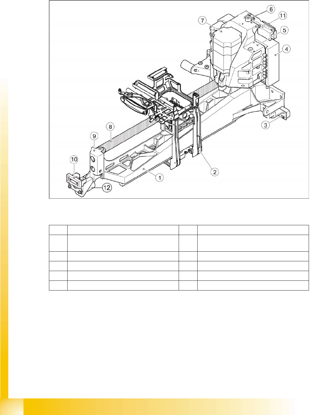
6-2: Mechanical axis structure – part 1 (D4 shown as example)
Legend
Mechanical Structure
With the help of a toothed belt drive, the rotary movement of the X-axis motor is directly converted into
a lengthwise movement of the placement head, in the X-direction.
The linear guide rails under the X-axis guide the head assembly plate and the placement head along the
X-axis.
The X-motor is cooled by a fan at the Y-axis pickup position and the motor temperature is also monitored
by a sensor.
1 Precision-cast gantry 7 X motor unit
2 Head mount with support for gantry head
distributor board
8 Toothed belt
3 Incremental encoder for Y-axis scale 9 Deflection unit
4 Primary part Y-linear motor 10 Y brake outside
5 Motor bracket X / heat sink (tab) Y motor 11 Y brake inside
6 Thrust bearing 12 Bumper X-axis outside