D-serie LEVEL II.pdf - 第54页
Communication and Control CAN Bus CAN Bus Terminating Resistors S tuden t Guide Advanced Level 2 SIPLACE D Series Communication and Control EN 05/2007 4-14 4.3.6 CAN Bus T erminating Resistors 4-11: Terminating resistors…
Communication and Control
CAN Bus Processor Board on the Gantry Head Distributor CAN Bus
Student Guide Advanced Level 2 SIPLACE D Series
EN 05/2007 Communication and Control
4-13
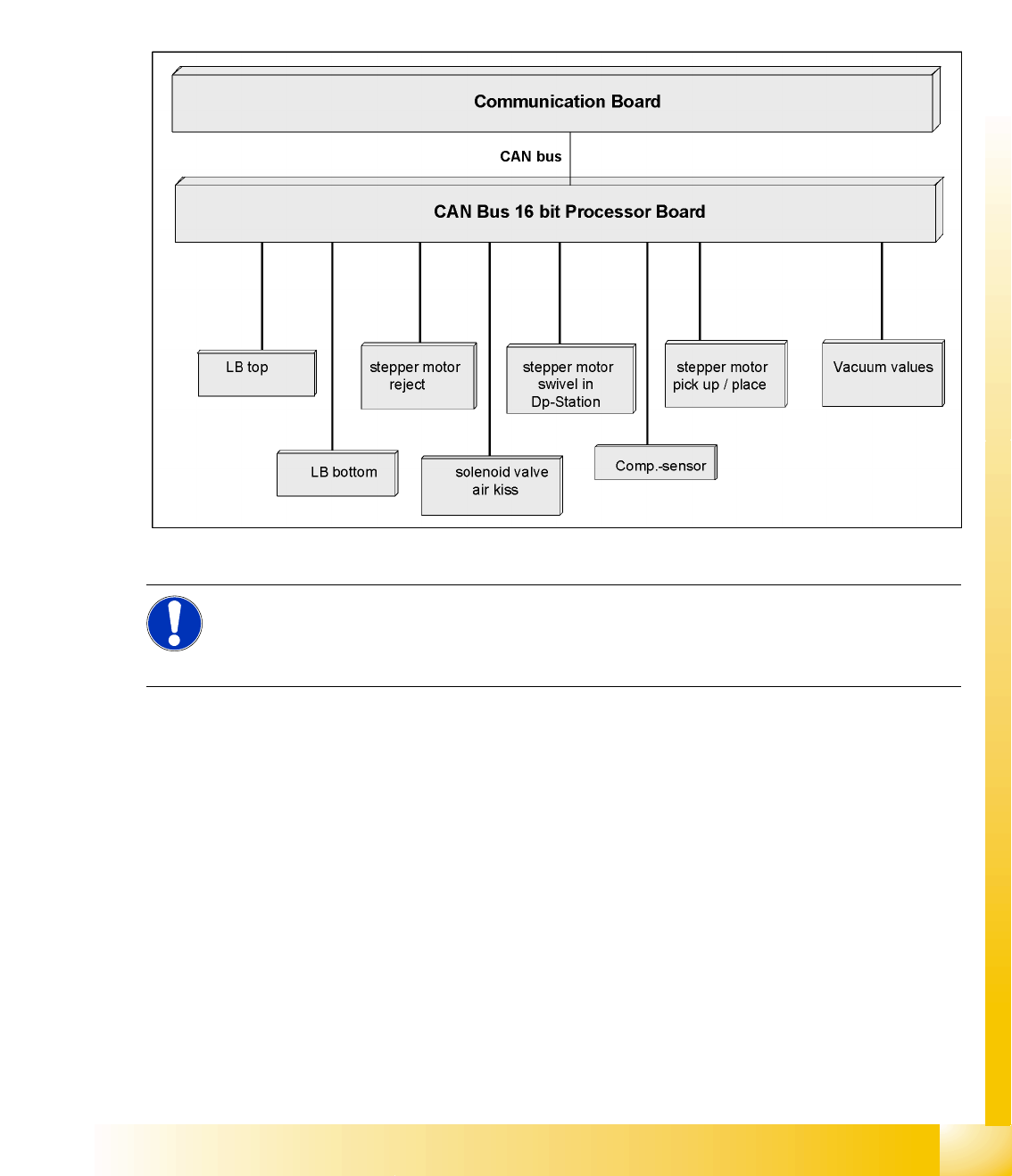
4.3.5 CAN Bus Processor Board on the Gantry Head Distributor
The TQM 167LC CAN bus processor board is connected to the head board. The processor board is used
at different places in the machine. If the processor board on the head board, the firmware provides at
the processor board the control of the head specific actuators and sensors no matter which head type is
installed.
4.3.5.1 CAN BUS-Controlled Functions on the C&P12 Head
The following overview shows various head functions, controlled by the CAN system. Thus, the CAN bus
controls the actuators and sensors of the C&P head.
4-10: CAN function on C&P head
NOTE:
The status of the 16 Bit PROCESSOR BOARD is indicated on the 7-segment display.
Normal status on the display is: Display shows slowly flashed " . (for description see
Section C&P12).
Communication and Control
CAN Bus CAN Bus Terminating Resistors
Student Guide Advanced Level 2 SIPLACE D Series
Communication and Control EN 05/2007
4-14
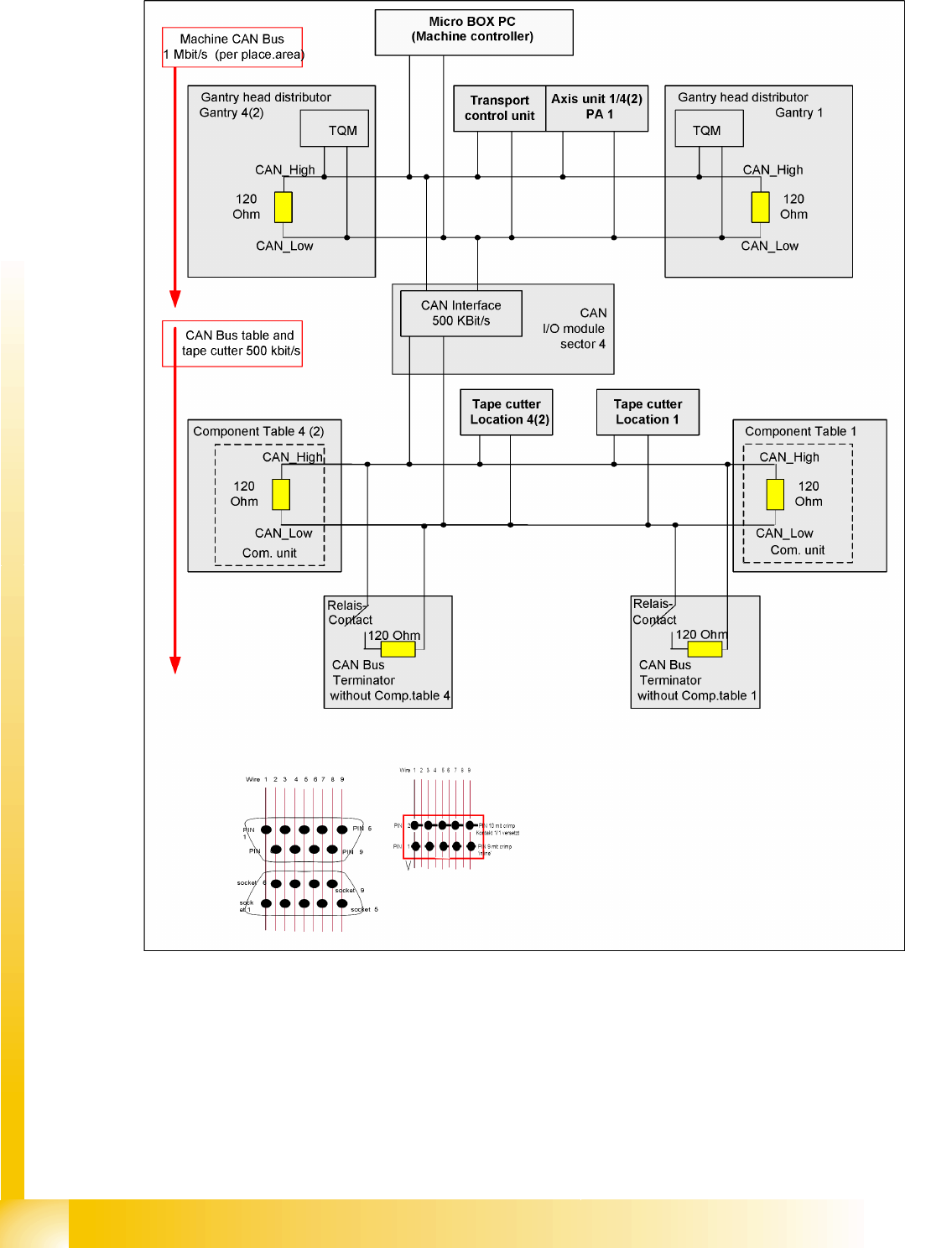
4.3.6 CAN Bus Terminating Resistors
4-11: Terminating resistors in D4 machine – CAN Bus for one placement area
Communication and Control
CAN Bus Terminating Resistors CAN Bus
Student Guide Advanced Level 2 SIPLACE D Series
EN 05/2007 Communication and Control
4-15
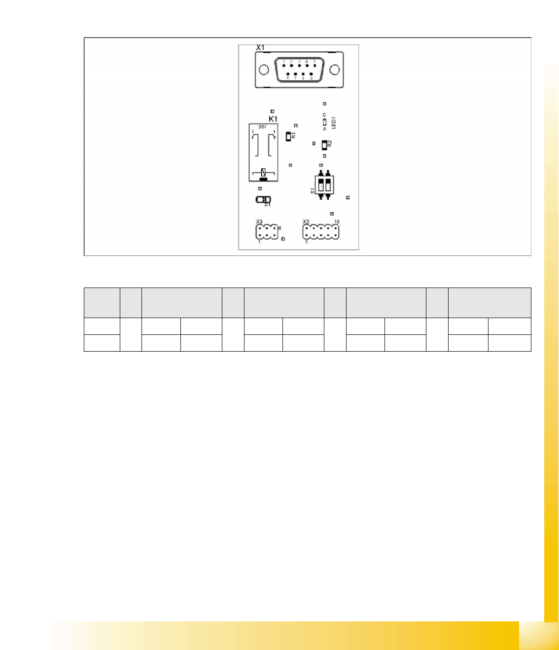
4.3.6.1 CAN Bus Terminator
The A3 assembly ensures that the CAN bus also functions with undocked changeover tables. During
undocking, a CAN terminating resistor is switched, which maintains the CAN bus function and
communication.
If the terminating resistance is measured with the machine switched off and the changeover tables
connected, you will be able to measure 30 Ohms at the Sub CAN bus (with 500kbit/s). Reason: There
are 4x 120 Ohm resistors switched parallel. When the machine is switched on, the resistors switched in
A3 will be deactivated.
There is an A3 assembly in each sector.
4-12: A3 assembly
*1
D1/D2: WPC and sector 1
*2
D1/D2: Sector 2
S
Feeder table plate
Sector 1
*1
Feeder table plate
Sector 2
*2
Feeder table plate
Sector 3
Feeder table plate
Sector 4
1 ON OFF ON OFF
2ON ON OFF OFF
CAN BUS terminator for changeover table (switch setting S1 on A3 assembly)