D-serie LEVEL II.pdf - 第116页
Axis Dynamics Axis Control Assemblies Axis Controller S tuden t Guide Advanced Level 2 SIPLACE D Series Axis Dynamics EN 05/2007 7-10 7.3.1 Axis Controller 7-8: View of the SIPLACE machine ax is controller A364 and its t…
Axis Dynamics
Zero Pulse at the Track Signal Encoder Axis Control Assemblies
Student Guide Advanced Level 2 SIPLACE D Series
EN 05/2007 Axis Dynamics
7-9
7.3 Axis Control Assemblies
The control circuit for control the X- and Y-axis in general consist of the following parts:
Axis board
Servo board (TDS) with braking board
3-phase AB linear motor (Y-axis)/
3 phase AC (rotation) motor (X-axis)
Measurement system (incremental scale and encoder (read unit))
To protect the motor of the X/Y-axes from overtemperature, these have an internal temperature sensor.
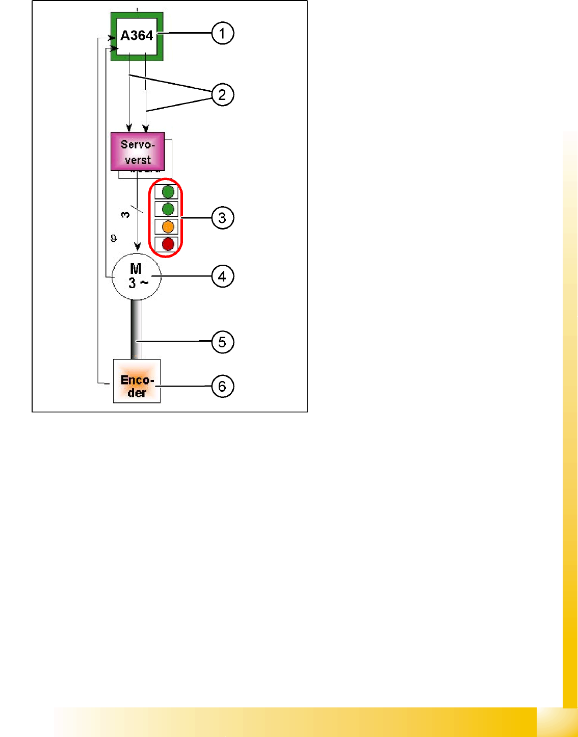
7-7: Parts "Axis control"
Legend
1. Axis Board A364
2. Control signals I
target
"W" and I
target
"U"
3. LED‘s on Servo board:
– Power supply ON
– Servo enable, it the enable signal from the
axis board.
– Display R.M.S. current limiter shorter than
2,5 s.
– Error: Over voltage, -current, -temperature
longer than 2,5 sec.
4. 3-phase AC linear motor (Y-axis) or 3-phase
servo motor with integrated temperature
sensor.
5. Between motor and incremental encoder exist
a fixed mechanically connection.
6. Incremental encoder: transmit the exact
position of the axis The track signals are the
only feedback signals for the axis control
system.
The servo board directly controls the linear motor
(intermediate circuit voltage 250 V) or servo
motor.
Axis Dynamics
Axis Control Assemblies Axis Controller
Student Guide Advanced Level 2 SIPLACE D Series
Axis Dynamics EN 05/2007
7-10
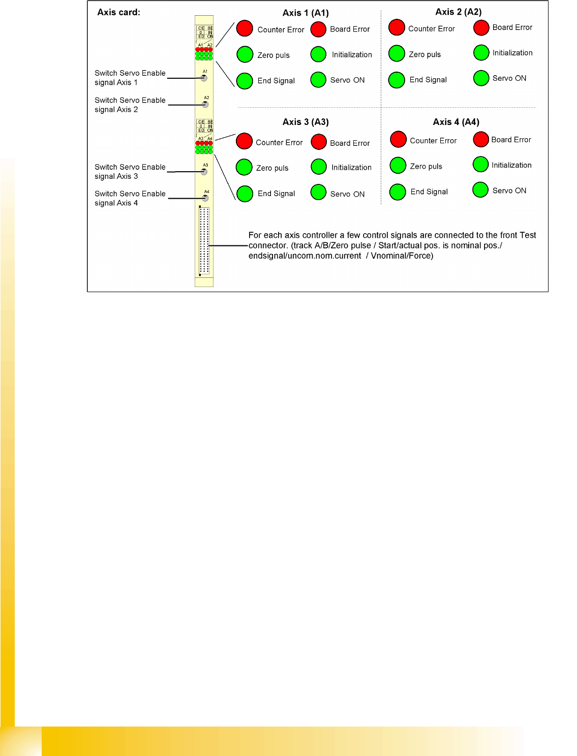
7.3.1 Axis Controller
7-8: View of the SIPLACE machine axis controller A364 and its test signals
The axis controller receives the target position and the start signal from the MC. All relevant calculations
and control actions are performed by the axis controller.
The axis controller A364 in the SIPLACE machine is socket coded. This means that no address switches
need to be set when parts are replaced.
The communication and axis control functions are handled by the axis controller.
The relevant
BIOS SW is responsible
Application 1, Application 2
Due to the various types of drives (motors), you will need different entries for the control parameters.
This results in different firmware versions for the axis types.
Axis Dynamics
Servo Amplifier TBS .. and SDS ... Axis Control Assemblies
Student Guide Advanced Level 2 SIPLACE D Series
EN 05/2007 Axis Dynamics
7-11
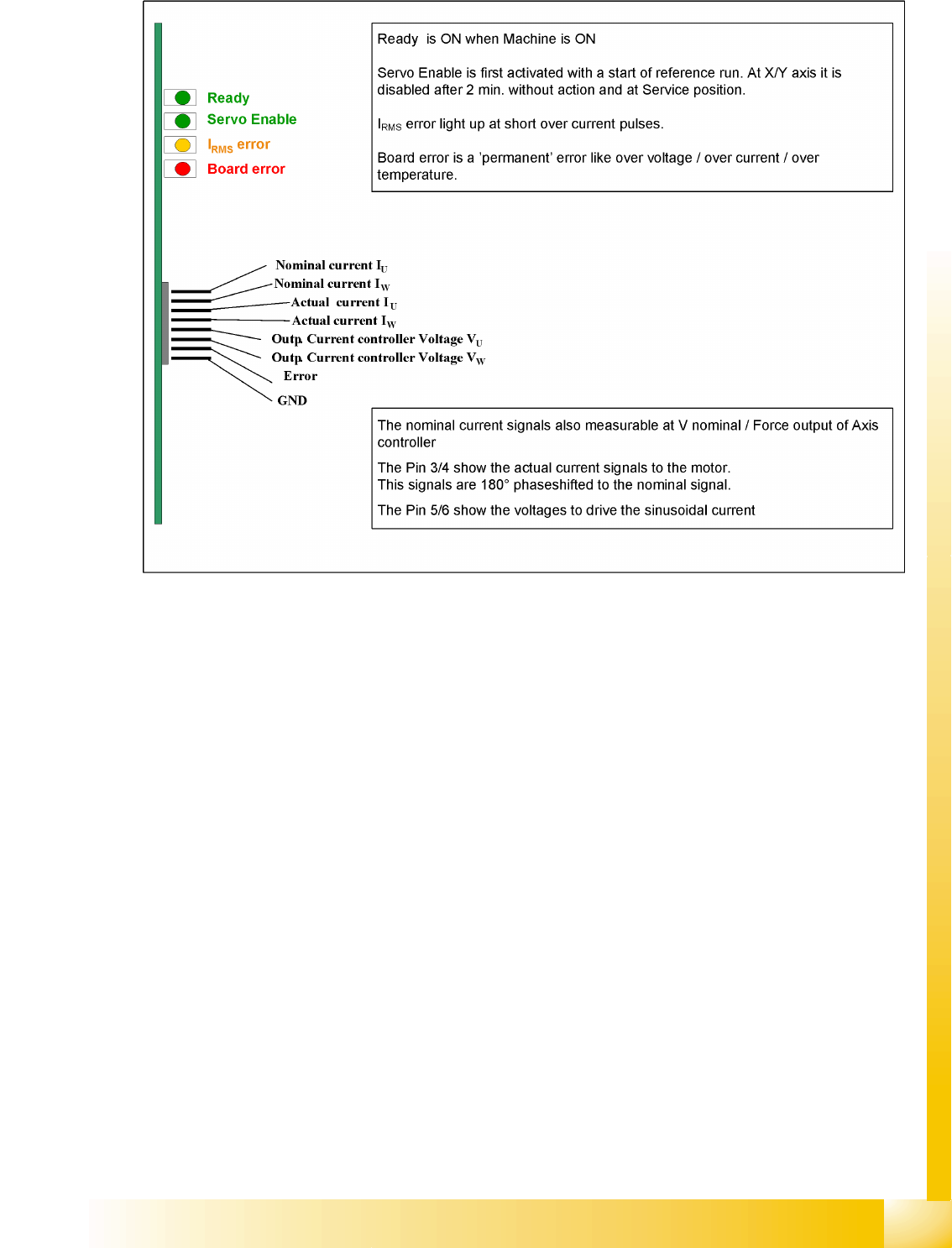
7.3.2 Servo Amplifier TBS .. and SDS ...
7-9: Servo amplifier
Servo amplifiers of type TBS are used for the X/Y and star axes, while SDS servo amplifiers are used
for the Z and DP axes. Depending on the individual input, SDS servo amplifiers can process voltages of
up to 60 VDC or 120 VDC.
This SDS and TBS Servo amplifiers are to reset by Servo disable / Servo enable at Axis controller board.
All servos are individually set for the maximum motor current of the drive unit connected. This means the
servo amplifiers have to be mounted specifically for the current axis type.
Measurement pin MP7:
In case of an error on the Servo amplifier, it is possible to measure on the analog output pin MP7 different
voltages to determined the error.
Overvoltage -1 V
Overcurrent -2 V
Overtemperature -3 V
Nominal current exceeded -4 V