D-serie LEVEL II.pdf - 第55页
Communication and Control CAN Bus Terminating Resistors CAN Bus S tude nt Guide Advanced Level 2 SIPLACE D Series EN 05/2 007 Communication and Control 4-15 4.3.6.1 CAN Bus T erminator The A3 assembly ensures th at the C…
Communication and Control
CAN Bus CAN Bus Terminating Resistors
Student Guide Advanced Level 2 SIPLACE D Series
Communication and Control EN 05/2007
4-14
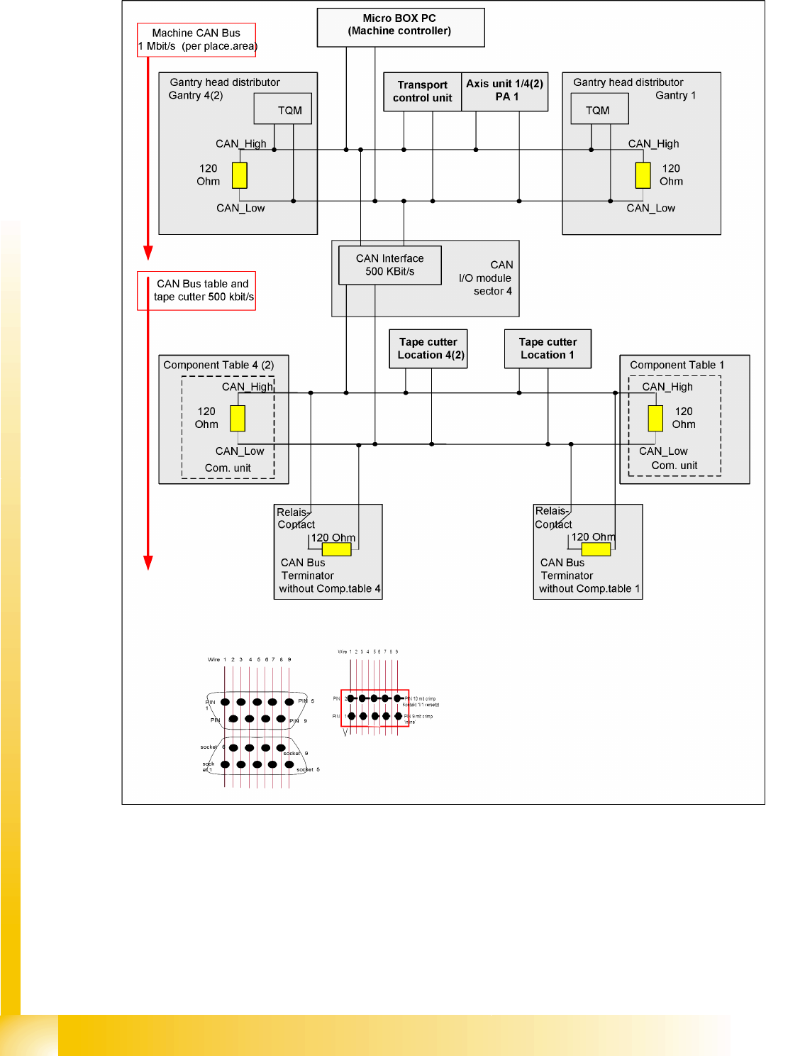
4.3.6 CAN Bus Terminating Resistors
4-11: Terminating resistors in D4 machine – CAN Bus for one placement area
Communication and Control
CAN Bus Terminating Resistors CAN Bus
Student Guide Advanced Level 2 SIPLACE D Series
EN 05/2007 Communication and Control
4-15
4.3.6.1 CAN Bus Terminator
The A3 assembly ensures that the CAN bus also functions with undocked changeover tables. During
undocking, a CAN terminating resistor is switched, which maintains the CAN bus function and
communication.
If the terminating resistance is measured with the machine switched off and the changeover tables
connected, you will be able to measure 30 Ohms at the Sub CAN bus (with 500kbit/s). Reason: There
are 4x 120 Ohm resistors switched parallel. When the machine is switched on, the resistors switched in
A3 will be deactivated.
There is an A3 assembly in each sector.
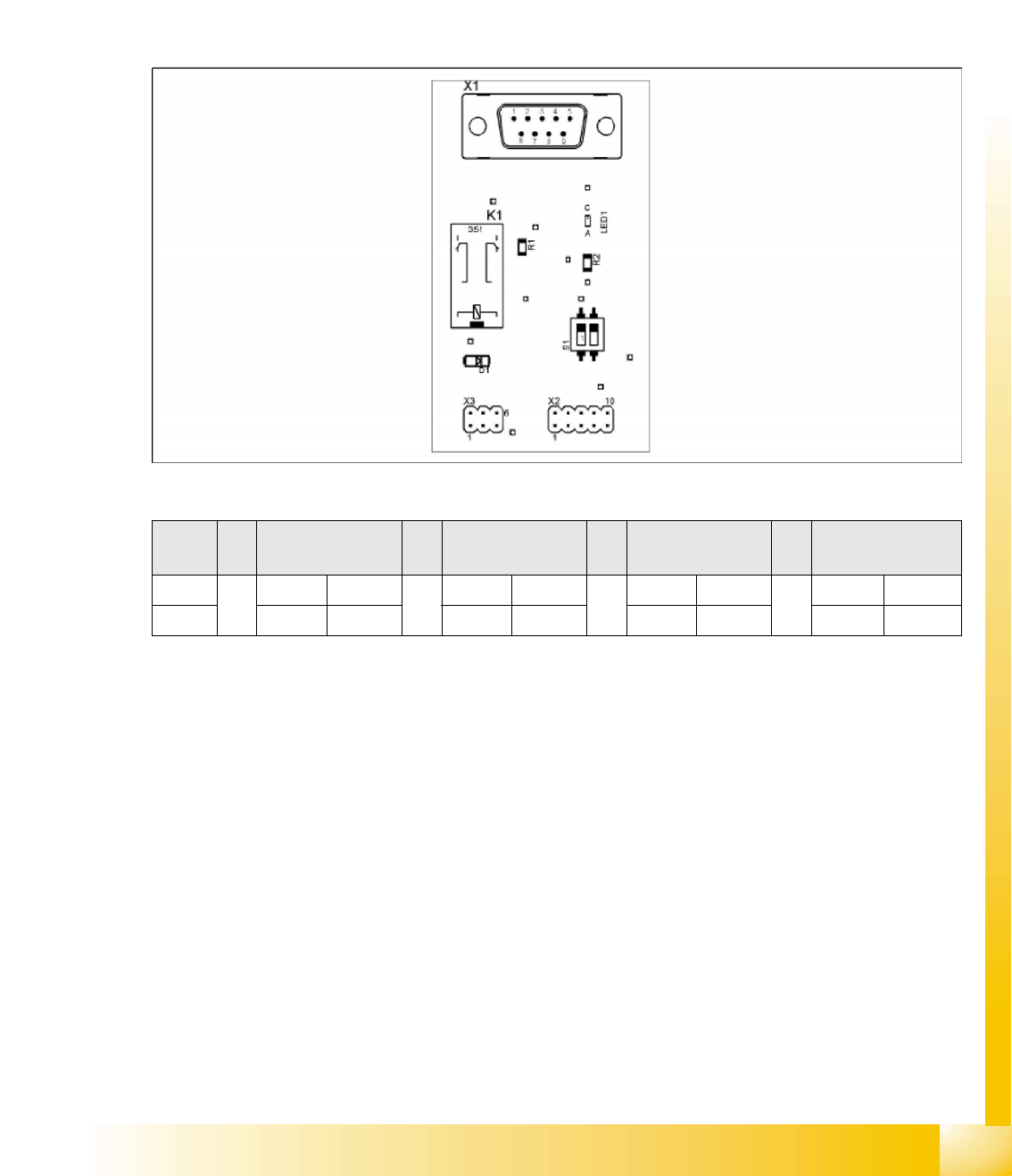
4-12: A3 assembly
*1
D1/D2: WPC and sector 1
*2
D1/D2: Sector 2
S
Feeder table plate
Sector 1
*1
Feeder table plate
Sector 2
*2
Feeder table plate
Sector 3
Feeder table plate
Sector 4
1 ON OFF ON OFF
2ON ON OFF OFF
CAN BUS terminator for changeover table (switch setting S1 on A3 assembly)
Communication and Control
CAN Bus CAN I/O Module (SLIO) - SIPLACE D4
Student Guide Advanced Level 2 SIPLACE D Series
Communication and Control EN 05/2007
4-16
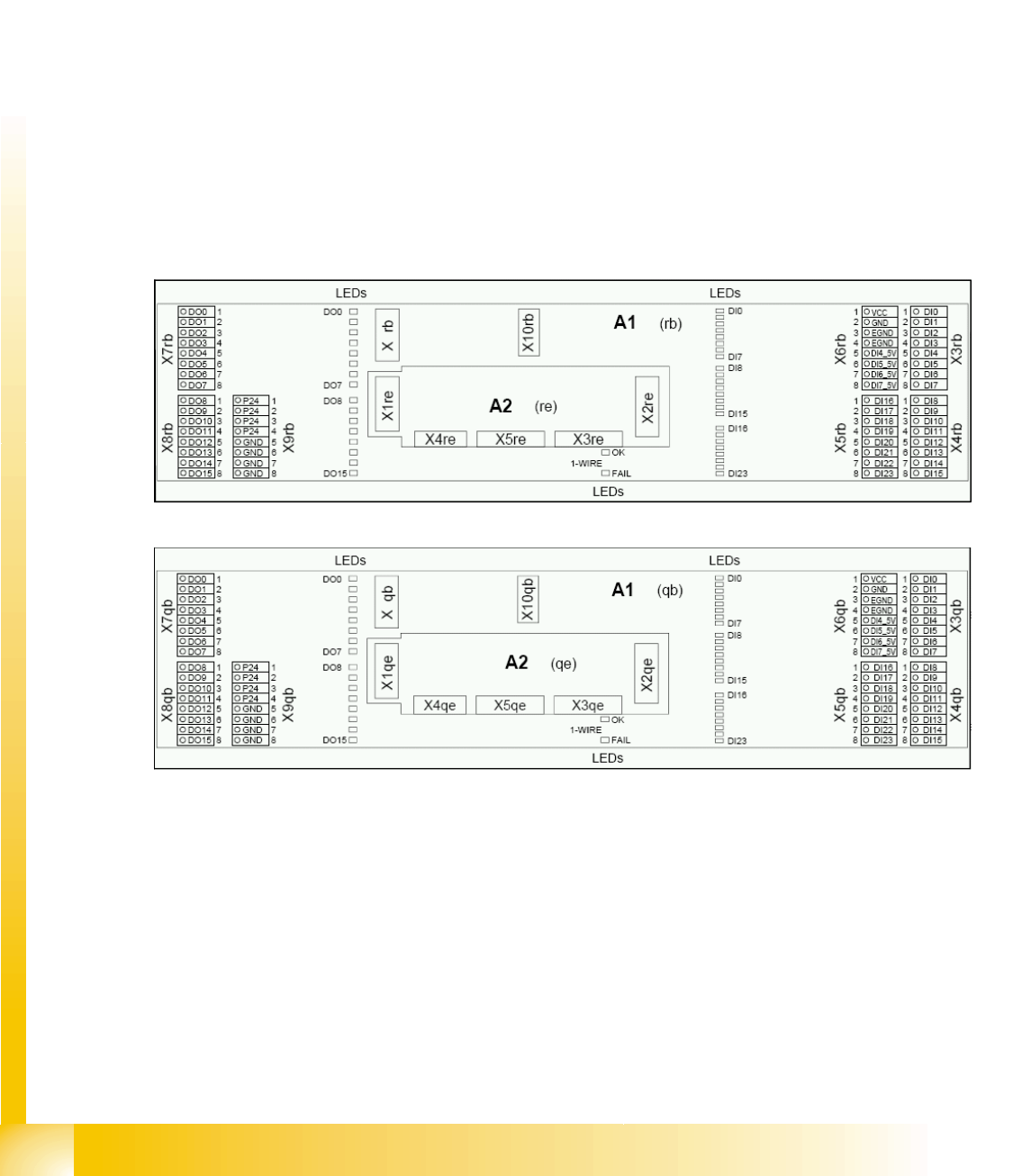
4.3.7 CAN I/O Module (SLIO) - SIPLACE D4
There are 2 CAN Bus I/O modules in the D4 machine. Both modules are absolutely identical and are
located in sectors 2 and 4.
Function
Micro controller with integrated CAN controller
Data memory
Program memory (flash)
CAN interface with 9 pin connector and address alignment
16 digital Output 24 V with status LED
24 digital Input 24 V with status LED
Download interface
Power supply 24 V
Extension on I/O module for the CAN interface (changeover tables)
8 digital inputs can be logically linked with the help of a FPGA (freely programmable gate array). The
FPGA is used for incoming security messages.
4-13: I/O module sector 2
4-14: I/O module sector 4