D-serie LEVEL II.pdf - 第160页
Component Handling Optional Extension on the COT Fixtures for S-Feeders S tuden t Guide Advanced Level 2 SIPLACE D Series Component Ha ndling EN 05/2007 9-10 9.3.4 Fixtures for S-Feeders 9.3.5 Additional Communication un…
Component Handling
Compressed Air Supply for Bulkcase Feeders Optional Extension on the COT
Student Guide Advanced Level 2 SIPLACE D Series
EN 05/2007 Component Handling
9-9
9.3.3 Compressed Air Supply for Bulkcase Feeders
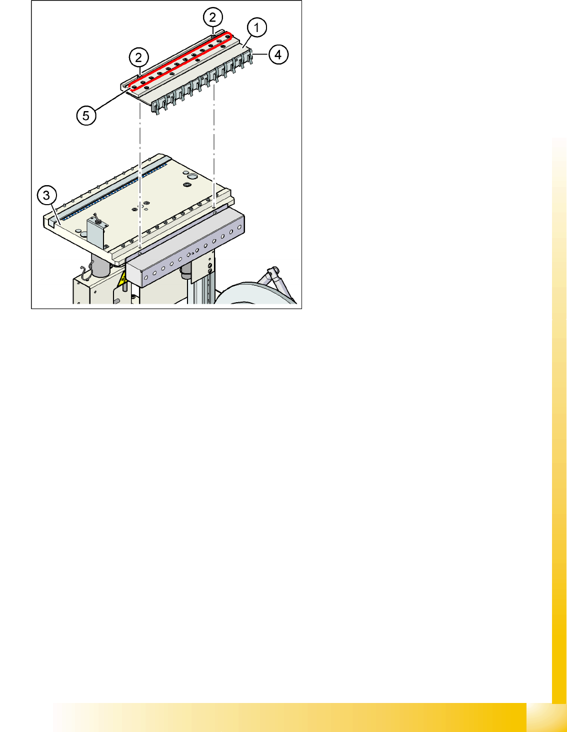
9-5: Compressed air supply for bulkcase feeders
Legend
1. Compressed air distributor
2. 2 x screw DIN 912, M8x20
3. Feeder table plate
4. Brackets
5. Compressed air connections for bulkcase
feeders
Bulkcase feeders require compressed air. The
optional compressed air supply for bulkcase
feeders is available for this purpose.
Installation is easy. The compressed air distributor
(1) is fixed with two screws (2) to the changeover
table (3). The compressed air distributor is then
connected to the component trolley compressed
air supply. At the back of the compressed air
distributor, there is a row of brackets (4). These fix
the bulkcase feeder modules to the changeover
table, ensuring optimum compressed air supply.
Component Handling
Optional Extension on the COT Fixtures for S-Feeders
Student Guide Advanced Level 2 SIPLACE D Series
Component Handling EN 05/2007
9-10
9.3.4 Fixtures for S-Feeders
9.3.5 Additional Communication unit for splice detection
9.3.6 Waffle Pack Changer (WPC)
Perform the following steps to fit a WPC4 into a D1 machine:
X Remove the changeover table in location 1.
X Remove the empty-tape duct assembly.
X Remove the waste slide.
X Remove the changeover table stopper.
X Fit the fixed changeover table WPC4 and screw tight.
X Fit the empty-tape duct for 5 feeder locations.
X Insert the WPC, lower and align.
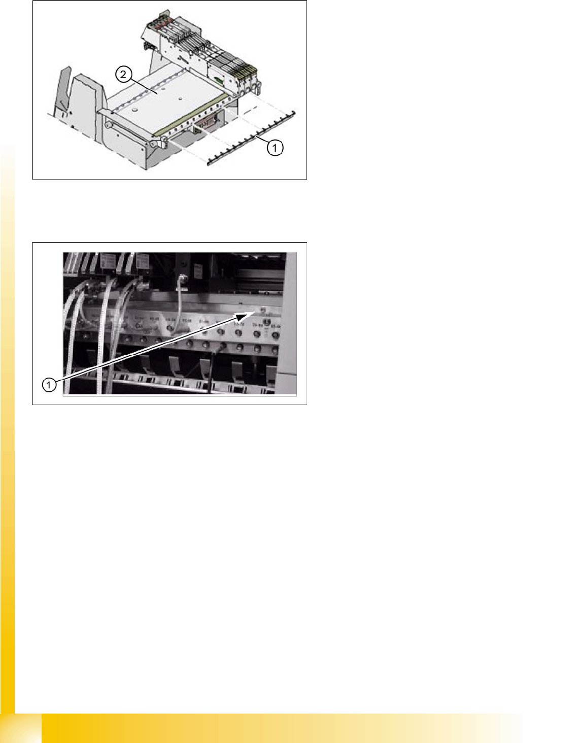
9-6: Feeder fixtures (HF shown as example)
Legend
1. Feeder fixtures
2. Changeover Table
The Feeder-Fixing is an additional mechanical
safety precaution. It prevents accidental
movement of the feeder on the changeover table.
It excludes a head crash risk with a wrong
positioned feeder. The feeder-fixation is mounted
on the front side of the changeover table. The
claws fix the feeder feet. A feeder clamp can be
installed for each of the component trolleys.
9-7: Additional Communication unit for splice detection
An additional communication unit for the option
Traceability with splice detection is necessary.
The splice sensors on the communication unit
inform the station software when a new
component lot (reel) is spliced on. This sets the
new fill level for this component automatically.
Legend
1. The additional communication unit is screwed
into place, together with the changeover table
communication unit.
Component Handling
Overview of Pneumatic Cutter with Empty Tape Duct Pneumatic Tape Cutter
Student Guide Advanced Level 2 SIPLACE D Series
EN 05/2007 Component Handling
9-11
9.4 Pneumatic Tape Cutter
9.4.1 Overview of Pneumatic Cutter with Empty Tape Duct
The pneumatic cutter is fixed to the machine frame with four screws and forms a unit with the empty tape
duct. It separates plastic, aluminum and paper tapes up to a maximum pocket depth of 25 mm. The tape
clippings fall down the waste slide, into the waste tape container of the component trolley.
The empty tape duct is designed to cover the cutting edges of the cutter (to avoid risk of injury), to guide
the empty component tapes to the cutter, to integrate the component reject container and accommodate
the C&P12 nozzle changer.
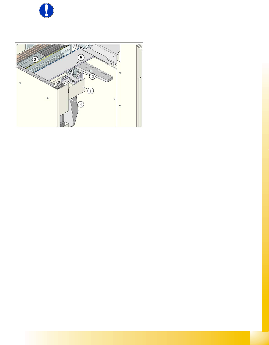
NOTE:
The D4 machine is used as an example to describe the pneumatic cutter.
9-8: Complete docking unit
Legend
1. Cross bar
2. Tape cutter
3. Empty Tape Duct
4. Waste slide
5. Proximity switch