D-serie LEVEL II.pdf - 第79页
Energy and Compressed Air Supply Overview Pneumatic System Pneumatic System S tude nt Guide Advanced Level 2 SIPLACE D Series EN 05/2007 Energy and Compressed Air Supply 5-13 5.3.2 Overview Pneumatic System 5-9: Overview…

Energy and Compressed Air Supply
Pneumatic System Vacuum Generation at C&P Heads - General Information
Student Guide Advanced Level 2 SIPLACE D Series
Energy and Compressed Air Supply EN 05/2007
5-12
5.3 Pneumatic System
5.3.1 Vacuum Generation at C&P Heads - General Information
The air is supplied to the vacuum generator, which produces a vacuum using the venturi principle.
The venturi block actually consists of 2 separate venturi nozzles which produce vacuum for 2 circuits,
the holding circuit and the pick up / placement circuit.
The level of vacuum produced is dependent on a number of factors. The greatest influence on vacuum
generation is from the Venturi unit. Any leakage from or blockage within the system will result in working
inefficiently and therefore a reduction in the vacuum levels created. The Venturi unit must be absolutely
airtight and the nozzles in very good condition and of high quality.
One factor which can impair vacuum generation is the altitude. The higher above sea level a machine is
located, the low the ambient pressure will be in the room surrounding it. Therefore at high altitude low
vacuum levels are created, A SIPLACE machine in Munich, at an altitude of 500 m above sea level, can
generate a closed vacuum of approx. 870 mbar, while a machine at sea level in England would be able
to produce approx. 920 mbar.
Another factor influencing the vacuum values is the weather. Stormy, rainy days occur in periods of low
pressure. Vacuum generation during this weather may produce 880 mbar, while the same procedure a
week later, on a sunny day in a high pressure period, could well produce closed vacuum results of 900
mbar.
These 2 cases are only examples and no specific case / figures are used, but this just illustrates what
can happen. In any case, it is important that you use an efficient, high quality vacuum system.
The vacuum measurement board is located directly above the vacuum generator and measures the
vacuum values in the hold and pickup/placement circuits. Small tubes are attached to the back of the
Collect & Place head that measure the circuit pressures at the vacuum distributor. These tubes are
connected to pressure sensors. The analogue outputs of these sensors are supplied to A/D converters.
The resulting signals are then sent via the CAN-Bus to the machine controller.
Energy and Compressed Air Supply
Overview Pneumatic System Pneumatic System
Student Guide Advanced Level 2 SIPLACE D Series
EN 05/2007 Energy and Compressed Air Supply
5-13
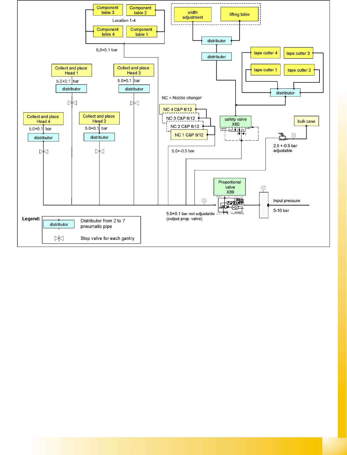
5.3.2 Overview Pneumatic System
5-9: Overview of pneumatic system/compressed air supply (D4)
Energy and Compressed Air Supply
Pneumatic System Pneumatic Unit
Student Guide Advanced Level 2 SIPLACE D Series
Energy and Compressed Air Supply EN 05/2007
5-14
5.3.3 Pneumatic Unit
5.3.3.1 Overview of Pneumatic Unit
The pneumatic unit is a fixed installation inside the machine. The unit is accessible via a door and
contains the complete compressed air supply for all consumer devices.
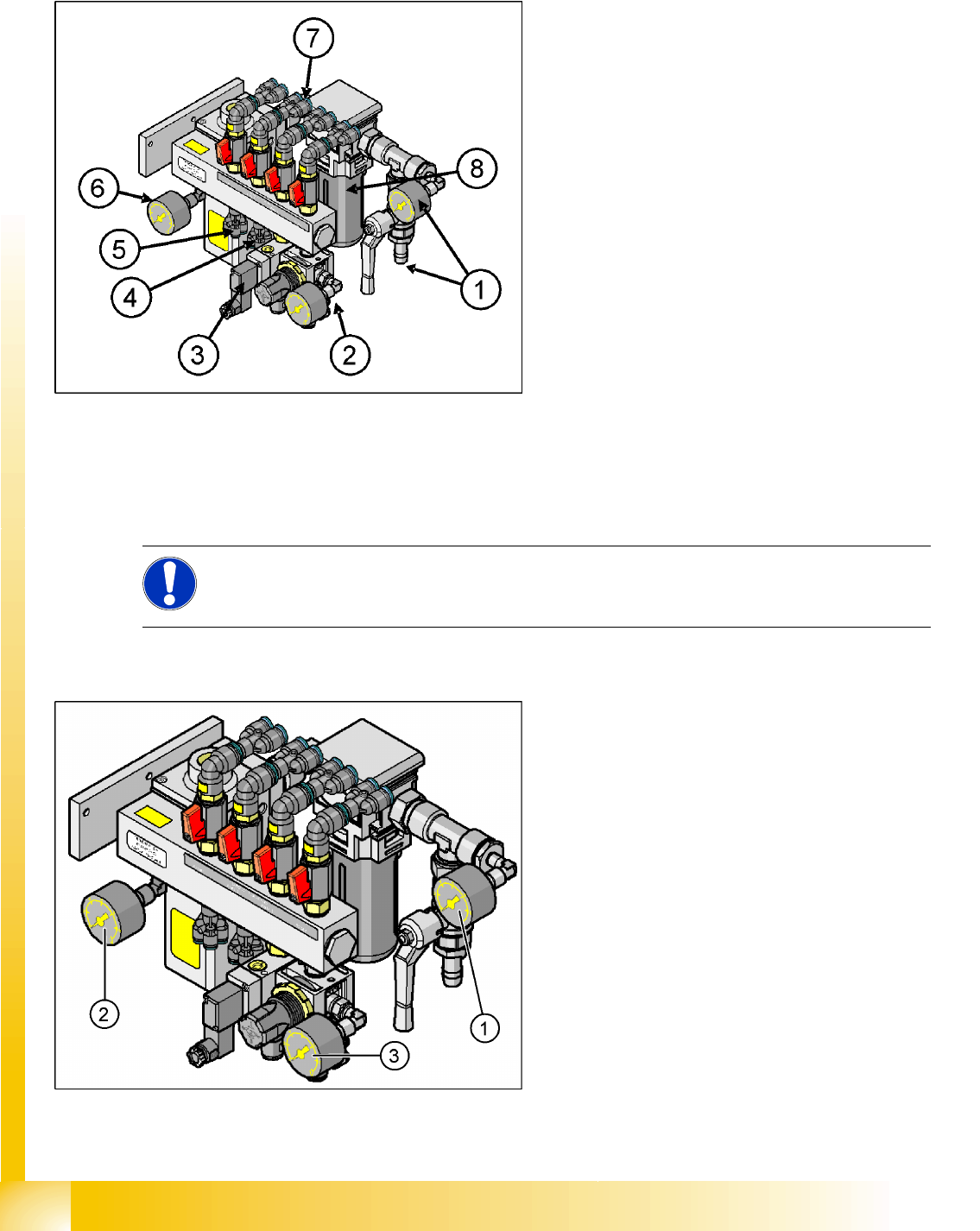
Manometer Arrangement
5-10: Pneumatic unit as rack module (D4)
Legend
1. Main compressed air connection with shutoff
valve and manometer
2. 4x connection for bulkcase feeder with
manometer, manually adjustable (2.5 bar),
location 1 - 4
3. 4x connection for cutters, location 1 - 4
2x connection for conveyor lifting table
4. 4x connection for nozzle changer
5. 4x connection for docking/undocking
changeover table
6. Electronic control valve with manometer for
incoming pressure
7. 4x connection for gantries 1 - 4, vacuum
generation C&P head with shutoff valves
8. Compressed air filter (you might need a
suitable tool to open it)
NOTE: Different pressure
Note the different pressure for the nozzle changer of the D4 machine, which is considerably
higher (5.1 +/- 0.1 bar) than that for the nozzle changers of D1/D2 machines.
5-11: Main pneumatic unit: manometer arrangement (D4)
Legend
1. Manometer input pressure (5 – 10 bar)
2. Manometer regulated supply pressure
5.0 +0.1 bar for placement heads
3. Manometer for reduced pressure 2.5 +/0.5 bar
(manually adjustable)