D-serie LEVEL II.pdf - 第59页
Communication and Control Communication Siplace Vision SIPLACE Vision S tude nt Guide Advanced Level 2 SIPLACE D Series EN 05/2 007 Communication and Control 4-19 4.3.9 Communication Siplace Vision 4-17: Overview Siplace…
Communication and Control
CAN Bus CAN Bus Communication with Axis Controller
Student Guide Advanced Level 2 SIPLACE D Series
Communication and Control EN 05/2007
4-18
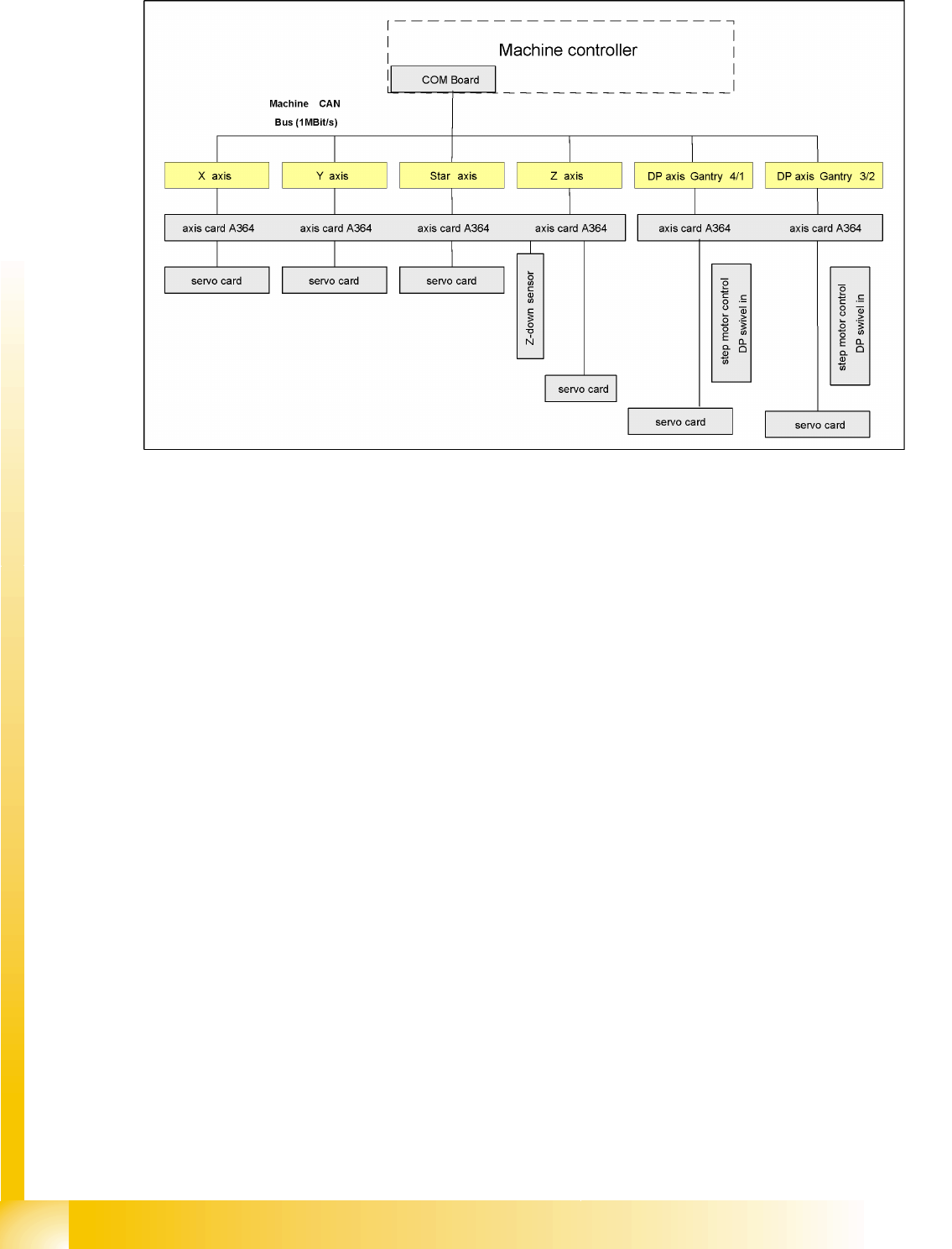
4.3.8 CAN Bus Communication with Axis Controller
4-16: Overview axis controller
In previous Siplace placement machines, the communication and data flow between axis controller and
machine controller was achieved using the SMP bus. From the HF machine generation onwards, the
SMP bus is no longer used with the axis system.
The communication between the axis controller modules is now achieved using the CAN Bus. All the
information exchanged between these modules is transmitted via the CAN bus (e.g. axis parameters,
target position, end position signal ...). This means that the number of individual telegrams increases
significantly over time, compared to the amount of data in older machine generations.
The axis control system is divided into:
Axis control I and II for gantry and main axes, plus
Axis control III for "remaining head axes".
Axis control I and II communicate directly with one another, via the interrupt lines for the anti-crash
monitoring system. The data communicated is the two Y gantry axis positions and the axis states.
Communication and Control
Communication Siplace Vision SIPLACE Vision
Student Guide Advanced Level 2 SIPLACE D Series
EN 05/2007 Communication and Control
4-19
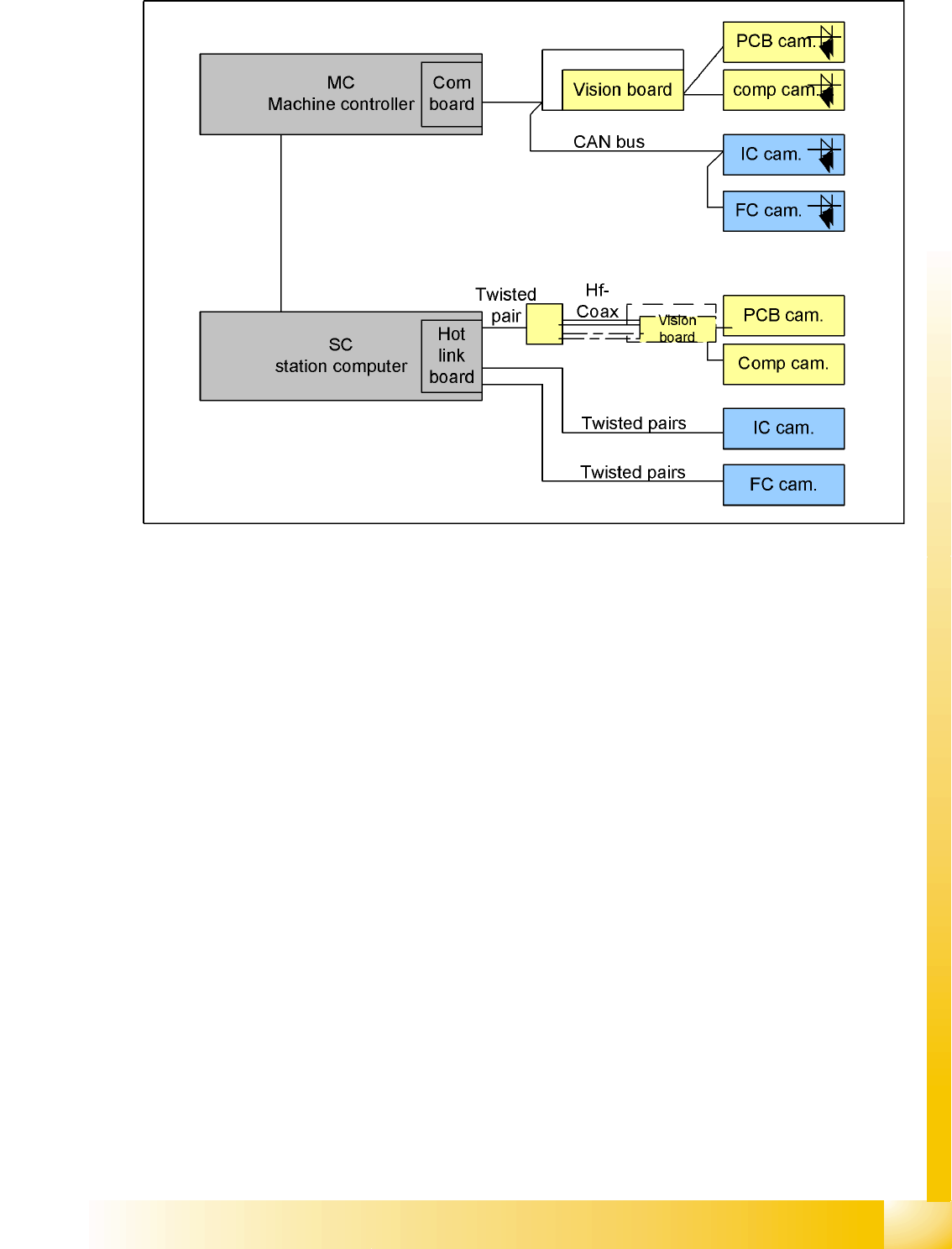
4.3.9 Communication Siplace Vision
4-17: Overview Siplace Vision
The communication between the computers is carried out via LAN cables. The MC sends the commands
for the image acquisition to the vision task of the station computer and receives the result of the
measuring. The MC also sends the illumination values for the corresponding CSs. The taken pictures
are sent digitally via the Hot link card to the vision task of the station computer. These evaluated results
are sent to the MC.
4.4 SIPLACE Vision
The digital SIPLACE Vision solution is another step towards the satisfaction of customer demands for
greater speed, flexibility and robustness.
Advantages of the digital Vision system:
Robust and fast computing algorithms
Flexible measurement processes
Intuitive graphical user interface
Geometric description of components at the machine
State-of-the-art digital camera hardware
Homogenous illumination of camera Field of view and components
Each C&P head has its own digital component camera.
Communication and Control
SIPLACE Vision Digital PCB Camera (Type 34)
Student Guide Advanced Level 2 SIPLACE D Series
Communication and Control EN 05/2007
4-20
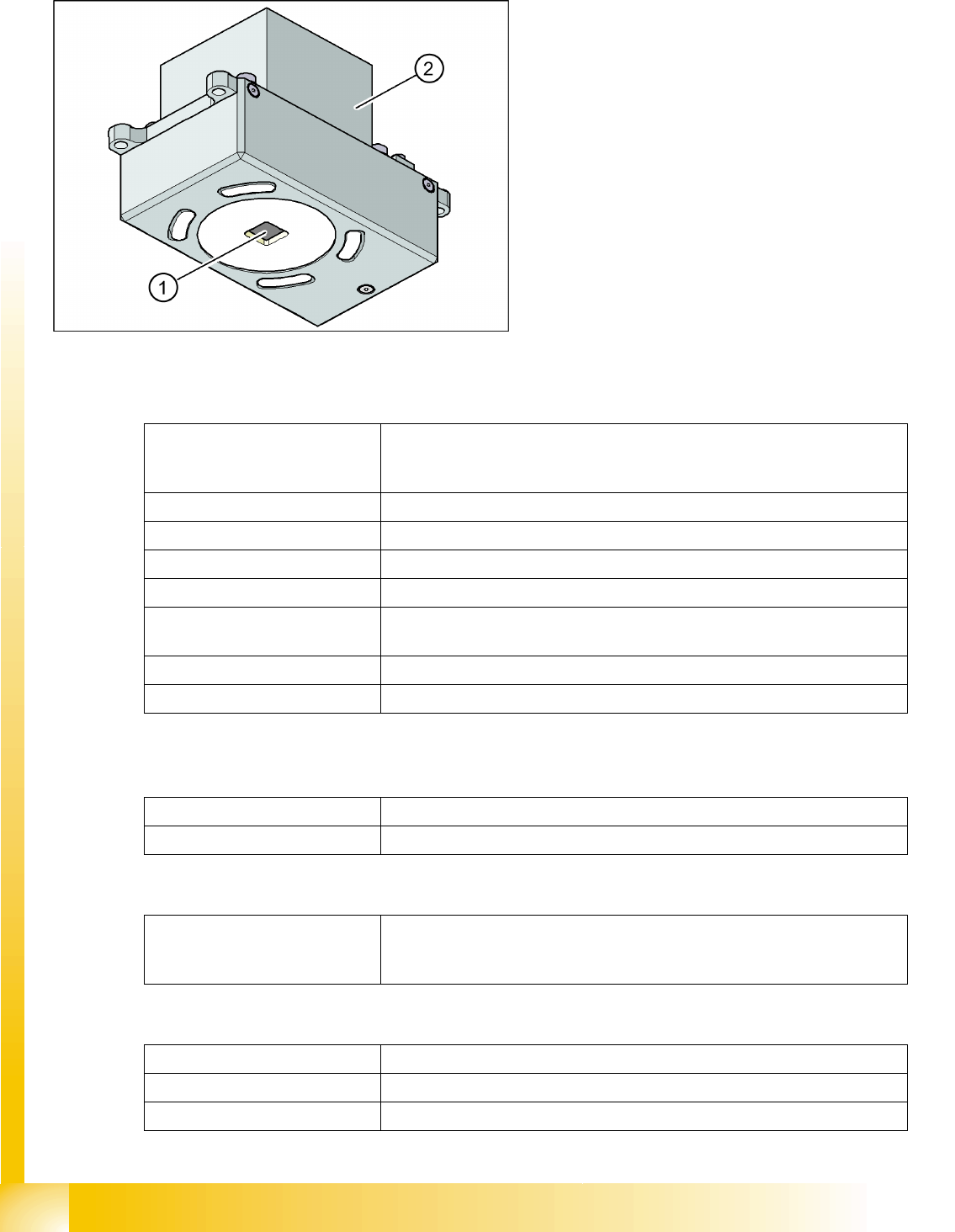
4.4.1 Digital PCB Camera (Type 34)
4.4.1.1 Technical Data
4.4.1.2 Fiducial Criteria
4-18: PCB camera under the gantry (X-axis)
Legend
1. PCB camera optics and illumination
2. Camera amplifier
PCB fiducials Up to 3 (panels and cluster panels),
Up to 6 for the option "long board" (optional fiducials are issued by the
optimization process).
Local fiducials Up to 2 per PCB (can be of different types)
Library archive Up to 255 fiducial types per panel
Image processing Edge detection method (single feature) based on gray values
Method of illumination Front-lighting (3 levels, programable as required)
Recognition time per
Fiducial/bad fiducial
20 ms - 200 ms
Field of view 5.78 x 5.78 mm2
Distance from the focus plane 28 mm
Technical Data for Camera Type 34
Determine 2 fiducials X/Y position, angle of twist, central PCB displacement
Determine 3 fiducials Additional: shearing, displacement separately in X and Y direction
Fiducial shapes Synthetic fiducials: circle , cross , square , rectangle , diamond , circular,
square and rectangular contours, doublecross
Pattern: any
Fiducial surface
Copper Without oxidation and soldering paste
Tin Warpage 1/10 of the structure width, with good contrast to surroundings