D-serie LEVEL II.pdf - 第181页
Modular Conveyor Functions in the PCB Conveyor Conveyor Settings S tude nt Guide Advanced Level 2 SIPLACE D Series EN 05/2007 Modular Conveyor 10-15 T o (2): Setting the Fixed Conveyor Side for " Extra Wide" Mo…
Modular Conveyor
Conveyor Settings Setting the Fixed Conveyor Side (Single and Dual Conveyor)
Student Guide Advanced Level 2 SIPLACE D Series
Modular Conveyor EN 05/2007
10-14
Connecting the Dual Conveyor Lifting Tables
X Remove the lifting table plate on conveyor lane 2 in PA1 and on lane 1 in PA2.
X Loosen the lockscrew(s) (4) and use a screwdriver to push the hexagonal circlip over the shaft on
lifting table 1.
X Do this for lifting tables in all placement areas. (lifting tables in the PA’s 180° turned.)
X Configure the new conveyor mode in SIPLACE Pro
To (3): Converting the Single Conveyor Mode Back to Flexible Dual Conveyor Mode
X Select the SITEST conveyor menu "Option and configuration" and then click on
Widen conveyor
to set the standard conveyor mode.
X The flexible conveyor side of conveyor 1 (right side fixed (track 1 left side fix)) is moved to a small
conveyor width.
X The SITEST SW ask to disconnect the lifting tables - Do so-.
X The SITEST SW will now use the conveyor control SW to move the fixed side of conveyor 2 (right
side is fixed (lane 1 left side fixed)) back to its standard position. Check the distances between the
two fixed conveyor lanes.
X Now adjust conveyor width of both tracks to desired values.
NOTE:
This option is only a mechanical function when you use the dual conveyor as a single conveyor.
The two lifting tables move parallel when they are connected.
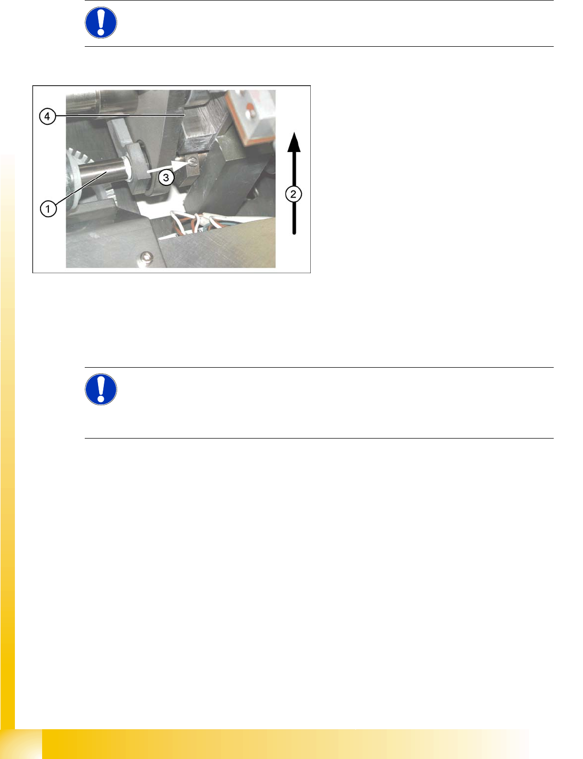
10-6: Lifting table
The drive shaft (1) is connected to the piston
rod of the pneumatic cylinder. This shaft
couple the second lifting table of the dual
conveyor. The lifting table drive shaft also has
an additional rod with a hexagonal circlip.
They secure the sleeve shaft in the desired
position.
Direction of transport (2)
Direction (3) in which the hollow shaft from
lifting table 2 (1 in PA 2) is to be moved to lifting
table 1 (2 in PA 2).
Lock screws (4)
NOTE:
When converting the dual conveyor to a single conveyor (flexible dual conveyor, connect the
lifting tables when requested to do so by SITEST (we recommend doing this without
compressed air supply to the lifting table).
This function is supported by SIPLACE Pro.
Modular Conveyor
Functions in the PCB Conveyor Conveyor Settings
Student Guide Advanced Level 2 SIPLACE D Series
EN 05/2007 Modular Conveyor
10-15
To (2): Setting the Fixed Conveyor Side for "Extra Wide" Mode
This mode is set in the menu
Change position of fixed rail
in the software.
The default positions for the fixed conveyor side (s) are predefined.
X Select
Option and configuration
from the SITEST conveyor menu and then click on
Change po-
sition of fixed rail,
to set the mode "extra wide".
X The fixed conveyor side TSP 2 (right side fixed (lane 1 left side fixed) remains in its position.
X The fixed conveyor side TSP lane 1 (right side fixed (lane 2 left side fixed) is moved 34 mm outwards.
The flexible conveyor side TSP lane 2 (lane 1 left fixed) can now be set to accommodate boards
which are wider than 216 mm (242 mm).
10.3.2 Functions in the PCB Conveyor
10.3.2.1 PCB Conveyor Monitoring
The board (PCB) transported from placement area 1 (PA1) into placement area 2 (PA2) may NOT be
removed from the intermediate conveyor by the operator. The PCB transport behavior is monitored
inside the machine and all PCB-relevant data is sent from PA1 to PA2. This means, for example, that
ink spot recognition and optical recognition of the 3rd PCB position fiducial is not performed in PA2.
NOTE:
This mode is possible for D-series machines with single or dual conveyors.
ATTENTION:
The end stoppers between the gantries need to be replaced with thinner stoppers, otherwise
you will not be able to perform placement on the fixed side, parallel to the pickup process in the
2nd gantry.
The lubrication nipples in the Y guidance slider are to be replaced with socket-head screws,
otherwise these could be damaged by a gantry crash.
ATTENTION:
After the conversion, you need to measure or calibrate the PCB reference corner and the
conveyor sides and then save these values in the machine data.
Modular Conveyor
Conveyor Settings Functions in the PCB Conveyor
Student Guide Advanced Level 2 SIPLACE D Series
Modular Conveyor EN 05/2007
10-16
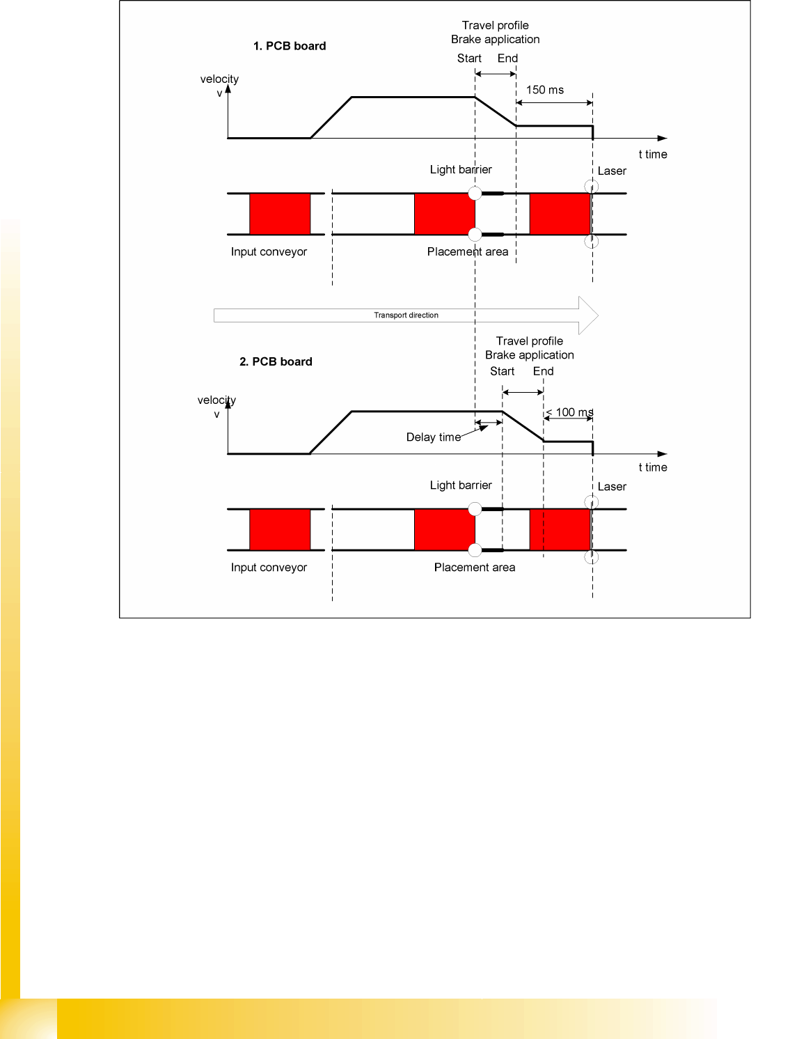
10.3.2.2 "Constant Transport Times Within Placement Area" Function
10-7: Diagram of board braking procedure
The automatic teaching at the beginning of the travel profile means that the stopper position is always
reached in the same time, irrespective of the board weight. This ensures that the transport time remains
constant.
Function of light barrier in the placement area
Laser light barrier activates
Board braking procedure starts
The light barrier in the placement area is responsible for initiating the braking procedure (travel profile)
via the conveyor software, once the board has been recognized. The software automatically "learns" the
first board by moving it in slow speed. The travel profile for braking the board is started at the right time,
to ensure that the board is reliably stopped at the laser light barrier, after a maximum of 100 ms.