D-serie LEVEL II.pdf - 第102页
Gantry Settings Description of Boards at Gantry S tuden t Guide Advanced Level 2 SIPLACE D Series Gantry EN 05/2007 6-16 6.3.3.2 Vision Processor Board (Digit al) The Vision processor board is mounted on the gantry head …
Gantry
Description of Boards at Gantry Settings
Student Guide Advanced Level 2 SIPLACE D Series
EN 05/2007 Gantry
6-15
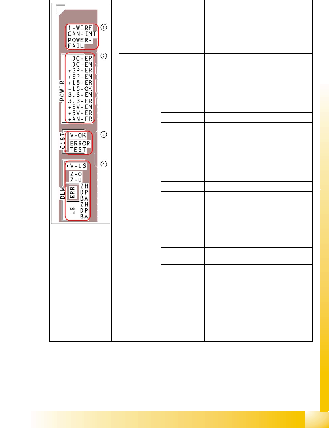
Description of LEDs on the Gantry Head Distributor
SM = stepping motor
Legend PCB labeling Operating
state LEDs
Description
1
CAN Bus
1-WIRE Not in use
CAN-INT OFF not used
POWER-FAIL OFF Error +24 V power supply (from
the main machine)
2
Status:voltage
supply
DC-ER OFF Error DC/DC converter
DC-EN ON Enable DC/DC converter
+SP-ER OFF Error +5V track encoder
+SP-EN ON Enable +5V track encoder
+15-ER OFF Error +15V
-15-OK ON -15V is OK
3.3-EN ON Enable +3.3V digital
3.3-ER OFF Error +3.3V digital
+5V-EN ON Enable +5 V digital
+5V-ER OFF Error +5V digital
+AN-ER OFF Error analog supply C167
3
Head CAN
processor
V-OK ON Internal voltage monitoring of
eSW
V-OK OFF
ERROR OFF Error eSW
TEST Flashing Timer eSW in operation
4
C&P head
functions and
signals
+V-LS ON OK + 15V light barrier
+V-LS OFF Error +15V light barrier
Z-O ON Z-axis is not up (in fork light
barrier)
Z-U ON Z down has switched
ERR-ZH OFF Overload SM valve positioning
drive, pick and place
ERR-DP OFF Overload SM swivel in, DP axis
ERR-BA OFF Overload SM valve adjustment
drive, reject
LS-ZH ON Light barrier SM valve
adjustment drive, pick and
place
LS-DP ON Light barrier SM DP axis,
swivel in
LS-BA ON Light barrier SM reject
Gantry
Settings Description of Boards at Gantry
Student Guide Advanced Level 2 SIPLACE D Series
Gantry EN 05/2007
6-16
6.3.3.2 Vision Processor Board (Digital)
The Vision processor board is mounted on the gantry head distributor board. This PCB is used for all
four gantries.
See also:
J DIP Switch on Vision Board [J6-17]
6.3.3.3 CAN 16 Bit Processor Board (TQ Module)
Description of 7-segment display (normal operation "." flashes):
After switch ON the machine appears " 0 " on the display
Display "b" --> BIOS was started.
Display flashes alternatively between "b" and "." --> no application available or unable to start
application.
Display " -I " and " I- " application was loaded.
"." flashes on the display --> ready for operation.
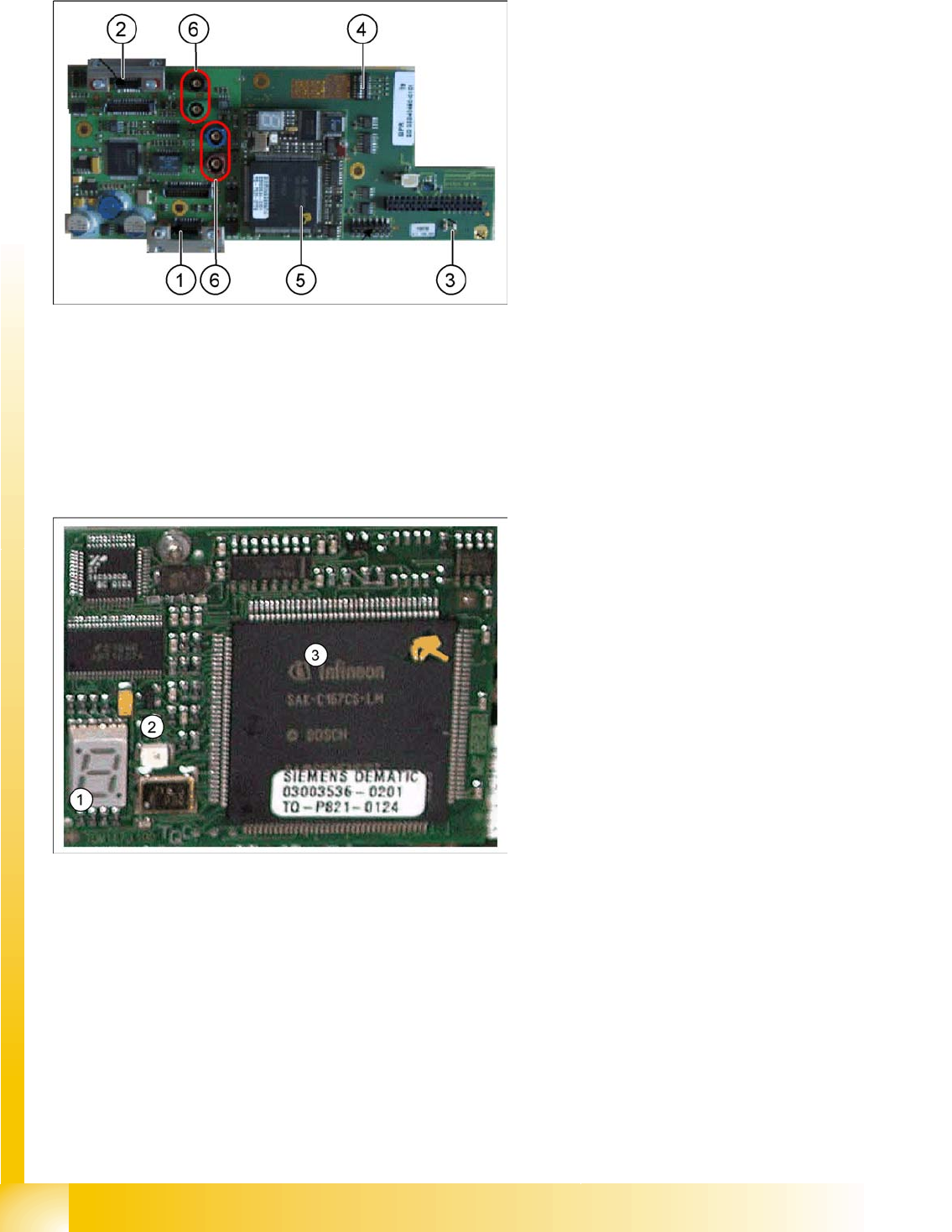
6-10: Vision processor board
Legend
1. X8 Connector illumination and video signals
PCB camera
2. X3 Connector illumination and video signals
component camera
3. LED‘s P15V - 15Volt / Vcc - Power supply
Vision board
4. DIP switch
5. CAN Processor 16 Bit (TQM Module)
6. Connector X22 - X24 Connectors for the video
cable to the trailing cable
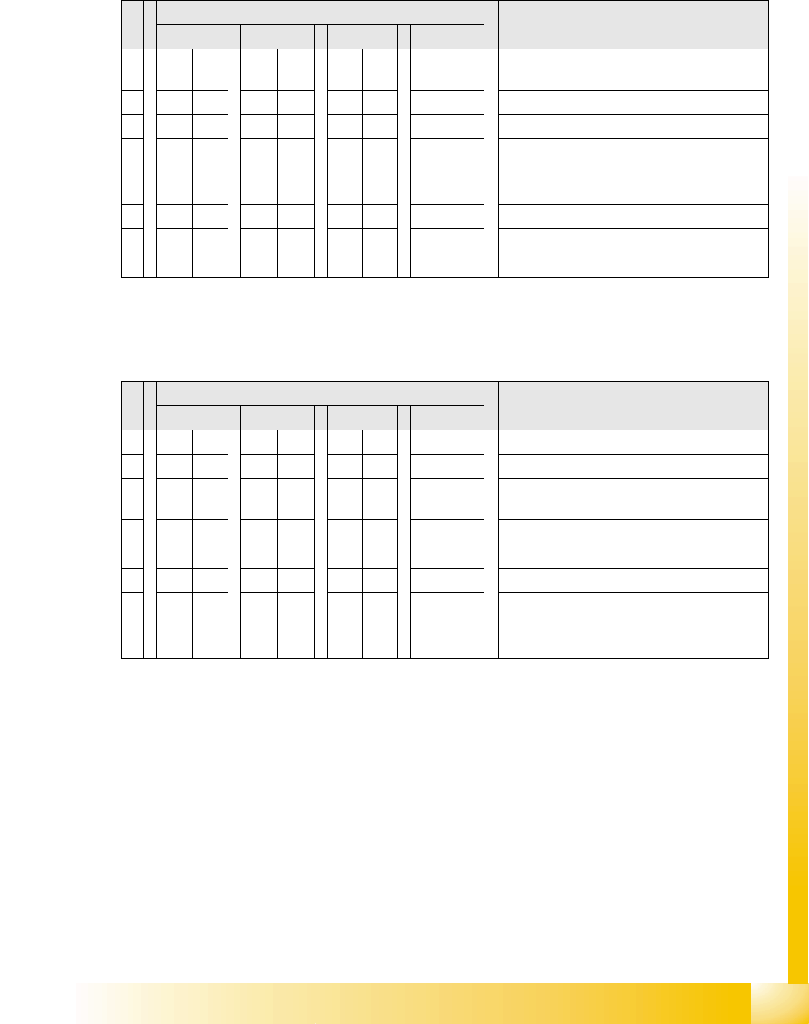
6-11: 16 bit processor (TQ module)
Legend
1. 7 Segment display
2. LED for manual RESET of processor
3. 16 Bit Processor
The 16 BIT CAN processor is used for various
different functions in the following units:
(see chapter Communication and Control as well)
Vision board, communication and control via
the CAN Bus to the vision computer.
Gantry head distributor, control of head
processes and vacuum
Gantry
Checking the DIP Switch Settings
Student Guide Advanced Level 2 SIPLACE D Series
EN 05/2007 Gantry
6-17
6.3.4 Checking the DIP Switch
6.3.4.1 DIP Switch on Vision Board
* You may find that not all gantries are available - this depends on the machine type.
6.3.4.2 DIP Switch on Gantry Head Distributor
* You may find that not all gantries are available - this depends on the machine type.
S Setting for gantry* Note
1 2 3 4
1 OFF OFF OFF OFF Boot mode – 16 bit CAN processor via
connector X11
2 OFF OFF OFF OFF Reset – 16 bit CAN processor on subboard
3 OFF ON OFF ON P0 - address switch 1 --> gantry
4OFF OFF ON ONP1 - address switch 2 --> gantry
5 OFF OFF OFF OFF WPE - write protect enable, currently
deactivated
6 OFF OFF OFF OFF CAN R - switch terminating resistor CAN bus
7ONONONONTest 1 - CAN 1 MBit/s --> ON
8ONONONONTest 0 - CAN IDs --> ON
S Setting for gantry* Note
1 2 3 4
1 OFF ON OFF ON P0 - gantry ID0 address switch 1 --> gantry
2OFF OFF ON ONP1 - gantry ID1 address switch 2 --> gantry)
3 OFF OFF OFF OFF S1 – switch for DLM head (delay switching on
LB down – Z-axis)
4 OFF OFF OFF OFF BL – activates boot loader for the serial port
5 OFF OFF OFF OFF Reset – CAN processor, 16 bit (TQM module)
6 OFF OFF OFF OFF C0 – currently no function
7 OFF OFF OFF OFF C1 – currently no function
8 OFF OFF OFF OFF S2 – switch for DLM head (currently no
function)