D-serie LEVEL II.pdf - 第119页
Axis Dynamics Checking the X-Axis Dynamics Gantry Axis Control S tude nt Guide Advanced Level 2 SIPLACE D Series EN 05/2007 Axis Dynamics 7-13 7.4.2.2 M easurement Setup with Adapter Board for A364 7-10: Measurement setu…

Axis Dynamics
Gantry Axis Control Track Signals and Zero Pulse
Student Guide Advanced Level 2 SIPLACE D Series
Axis Dynamics EN 05/2007
7-12
7.4 Gantry Axis Control
7.4.1 Track Signals and Zero Pulse
Track signals and zero pulse signals should be produced reliably by correct mechanical installation.
Should errors or malfunctions occur, check the machine as usual.
Previous incremental encoders show track A/B count signal amplitudes of 1.8 to 2.5 Vss.
New incremental encoders with 1 field optical systems have count signal amplitudes of 1.8 to 3.6 Vss.
7.4.2 Checking the X-Axis Dynamics
7.4.2.1 Overview
The inspection of dynamics occurs with the following signals:
Deviation of position
Uncommutated target current value
End signal ( Adapter board Axis in target position)
Actual position = target position signal (trigger for position deviation)
NOTE:
For further details, refer to the service manual for the respective machine.
NOTE:
For detailed information about checking the dynamics, refer to the settings instructions.
Before adjusting the axes, ensure that the machine has reached its operating temperature.
Switch the machine on at least 30 minutes before you begin work.
Axis Dynamics
Checking the X-Axis Dynamics Gantry Axis Control
Student Guide Advanced Level 2 SIPLACE D Series
EN 05/2007 Axis Dynamics
7-13
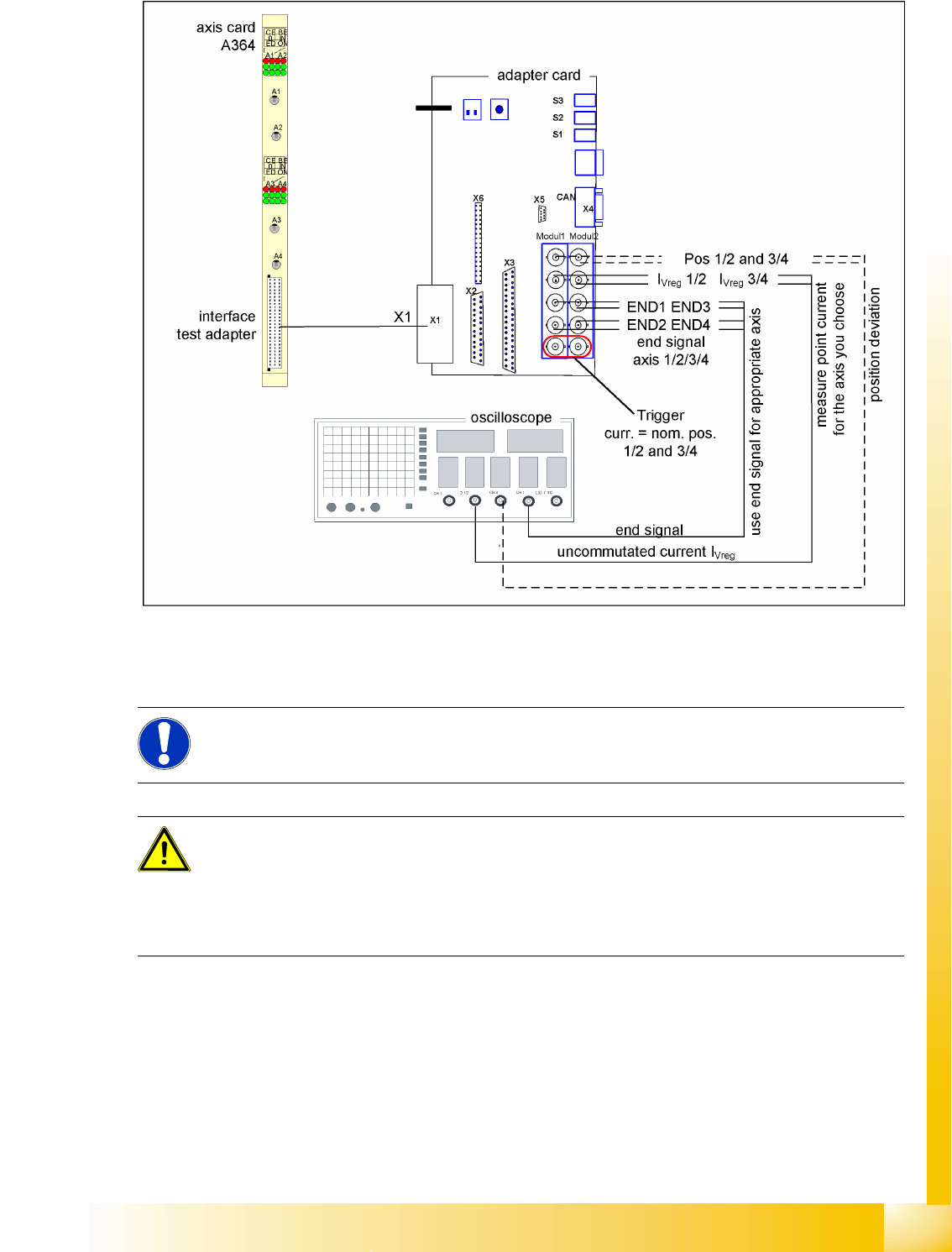
7.4.2.2 Measurement Setup with Adapter Board for A364
7-10: Measurement setup with axis test box
Additional connection at channel 4 could be the actual position = target position signal from trigger
m1/2 of the adapter board or the position deviation.
NOTE:
Measure the signals directly at the adapter board!
The position deviation issued there offers the benefit of showing the axis controller state.
ATTENTION:
When checking the dynamics, it may be sufficient if you check the travel times and overshoot
behavior of the axis with the SIPLACE axis tester (SAT) display and the values in the settings
tables.
However, when checking for errors, you will need to use a suitable oscilloscope for the dynamic
analysis.
Axis Dynamics
Gantry Axis Control Checking the X-Axis Dynamics
Student Guide Advanced Level 2 SIPLACE D Series
Axis Dynamics EN 05/2007
7-14
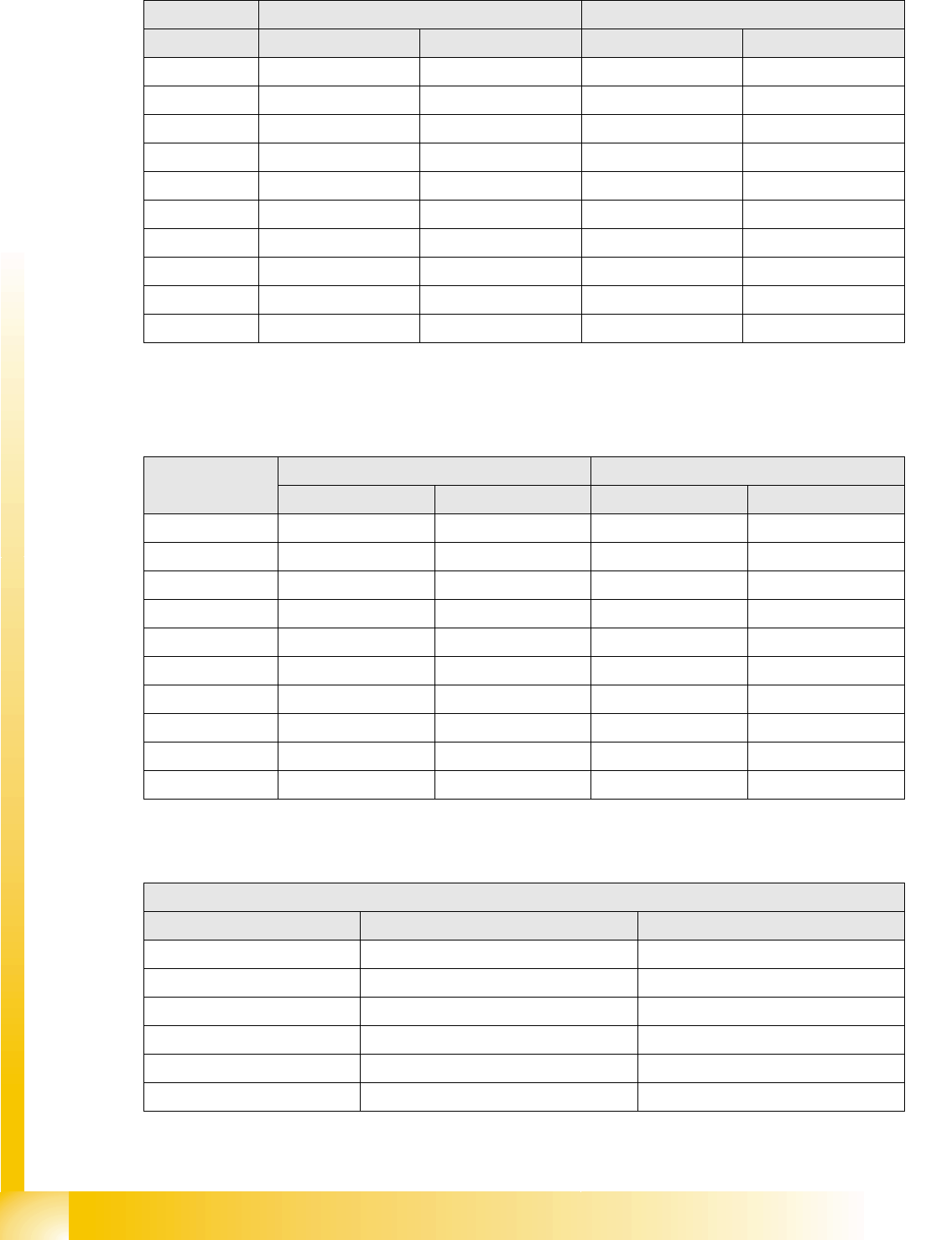
7.4.2.3 X-Axis Travel Time Table (D1/D2)
7.4.2.4 X-Axis Travel Time Table (D3)
In software version 603 the gantry travel times for the C&P head are about 5 ms faster than before:
7.4.2.5 X-Axis Travel Time Table (D4)
D1 machine: C&P6 or C&P12 + P&P D2 machine: C&P6 or C&P12
Range / digit Target time / ms Tolerance /ms Target time / ms Tolerance /ms
500 30 +/-5 33 +/-5
1000 33 +/-5 35 +/-5
2000 39 +/-5 37 +/-5
5000 48 +/-5 43 +/-5
15000 60 +/-5 56 +/-5
20000 66 +/-10 64 +/-10
50000 95 +/-10 88 +/-10
100000 126 +/-10 117 +/-10
200000 174 +/-15 159 +/-15
300000 214 +/-15 199 +/-15
Range / digit X gantry axis (C&P6, C&P12) X gantry axis with Twin head
Target time / ms Tolerance /ms Target time / ms Tolerance /ms
50021+/-525+/-5
100024+/-528+/-5
200030+/-534+/-5
500042+/-541+/-5
15000 53 +/-5 54 +/-5
20000 59 +/-5 59 +/-5
50000 82 +/-10 87 +/-10
100000 121 +/-10 125 +/-10
200000 169 +/-10 170 +/-10
300000 208 +/-15 209 +/-15
Travel times with 603 for X gantry axis, with the various different head configurations
X-axis gantry axis with DLM2 (C&P12)
Range / digit Target time / ms Tolerance /ms
500 32 +/-5
1000 34 +/-5
2000 38 +/-5
5000 45 +/-5
15000 56 +/-5
20000 63 +/-5