D-serie LEVEL II.pdf - 第58页
Communication and Control CAN Bus CAN Bus Communication with Axis Controller S tuden t Guide Advanced Level 2 SIPLACE D Series Communication and Control EN 05/2007 4-18 4.3.8 CAN Bus Communication with Axis Controlle r 4…
Communication and Control
CAN I/O Module (SLIO) - SIPLACE D4 CAN Bus
Student Guide Advanced Level 2 SIPLACE D Series
EN 05/2007 Communication and Control
4-17
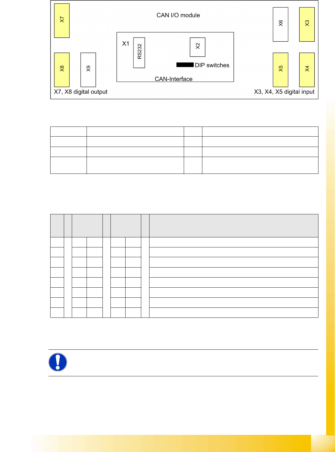
4-15: Overview CAN I/O module
Legend
DIP Switch on the Main- and Sub Distributor
There is an 8-fold DIP switch on the I/O module:
4.3.7.1 CAN I/O Module - Inputs and Outputs
X1 CAN interface X2 Analog interface, bootstrap loader interface
X3, X4, X5 Digital inputs 24V X6 Power supply 5V
X7, X8 Digital outputs 24V X9 Power supply 24V
RS232 Analog interface, bootstrap loader
interface
S Main
distributor
sector 2
Subdistrib
utor
sector 4
Comments
1ONONGateway (activate)
2OFF OFF ON: Slio emulation, OFF: CAN I/O module
3OFF OFF Speed (D1/D2: ON: 1Mbit/s), (D4: OFF: 500Kbit/s)
4ONOFFON: Location sector 2, OFF: Location sector 4 (D1/D2: OFF)
5OFF OFF Not in use
6OFF OFF ON: 1-Wire MA, OFF: 1-Wire PC
7OFF OFF Not in use
8OFF OFF Terminating resistor OFF (not used) (D1/D2: ON)
NOTE:
For the assignment of inputs and outputs on D-series machines, refer to the applicable circuit
diagrams or respective texts in the SITEST I/O menu.
Communication and Control
CAN Bus CAN Bus Communication with Axis Controller
Student Guide Advanced Level 2 SIPLACE D Series
Communication and Control EN 05/2007
4-18
4.3.8 CAN Bus Communication with Axis Controller
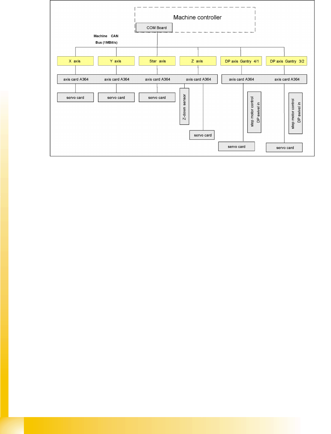
4-16: Overview axis controller
In previous Siplace placement machines, the communication and data flow between axis controller and
machine controller was achieved using the SMP bus. From the HF machine generation onwards, the
SMP bus is no longer used with the axis system.
The communication between the axis controller modules is now achieved using the CAN Bus. All the
information exchanged between these modules is transmitted via the CAN bus (e.g. axis parameters,
target position, end position signal ...). This means that the number of individual telegrams increases
significantly over time, compared to the amount of data in older machine generations.
The axis control system is divided into:
Axis control I and II for gantry and main axes, plus
Axis control III for "remaining head axes".
Axis control I and II communicate directly with one another, via the interrupt lines for the anti-crash
monitoring system. The data communicated is the two Y gantry axis positions and the axis states.
Communication and Control
Communication Siplace Vision SIPLACE Vision
Student Guide Advanced Level 2 SIPLACE D Series
EN 05/2007 Communication and Control
4-19
4.3.9 Communication Siplace Vision
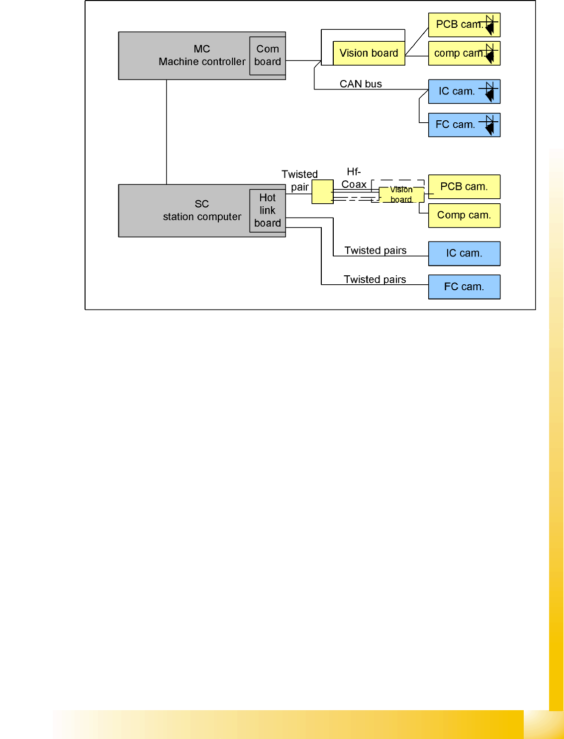
4-17: Overview Siplace Vision
The communication between the computers is carried out via LAN cables. The MC sends the commands
for the image acquisition to the vision task of the station computer and receives the result of the
measuring. The MC also sends the illumination values for the corresponding CSs. The taken pictures
are sent digitally via the Hot link card to the vision task of the station computer. These evaluated results
are sent to the MC.
4.4 SIPLACE Vision
The digital SIPLACE Vision solution is another step towards the satisfaction of customer demands for
greater speed, flexibility and robustness.
Advantages of the digital Vision system:
Robust and fast computing algorithms
Flexible measurement processes
Intuitive graphical user interface
Geometric description of components at the machine
State-of-the-art digital camera hardware
Homogenous illumination of camera Field of view and components
Each C&P head has its own digital component camera.