IPC-7351-2005_表面贴装焊盘布局设计和标准通用要求.pdf - 第23页
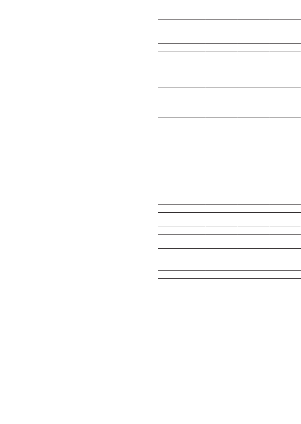
www.bzfxw.com T able 3-4 J Leads (unit: mm) Lead Part Minimum (Least) Density Level C Median (Nominal) Density Level B Maximum (Most) Density Level A Heel (to find Z dim) (J H ) 0.15 0.35 0.55 Round-off factor Round off t…
www.bzfxw.com
The IPC-7351 Library Documentation spreadsheets
included with this standard provide an analysis of tolerance
assumptions and resultant solder joints based on the fin-
ished land pattern dimensions. Tolerances for component
dimensions, the land pattern dimensions (fabrication toler-
ances on the interconnecting substrate), and the component
placement equipment accuracy are all taken into consider-
ation. These tolerances are addressed in a statistical mode,
and assume even distribution of the tolerances for compo-
nent, fabrication and placement accuracy.
Individual tolerances for fabrication (‘‘F’’) and component
placement equipment accuracy (‘‘P’’) are assumed to be as
given in spreadsheet documentation. These numbers may
be modified based on user equipment capability or fabrica-
tion criteria. Component tolerance ranges (C
L
,C
S
, and C
W
)
are derived by subtracting minimum from maximum
dimensions given. The user may also modify these num-
bers, based on experience with their suppliers.
The dimensions for minimum solder fillets at the toe, heel,
or side (J
T
,J
H
,J
S
) have been determined based on industry
empirical knowledge and reliability testing. Solder joint
strength is greatly determined by solder volume. An
observable solder fillet is necessary for evidence of proper
wetting. Thus, the values in the library documentation
spreadsheets usually provide for a positive solder fillet.
Nevertheless, if the user of any of the three land pattern
geometry variations desires a more robust process condi-
tion for placement and soldering equipment, individual ele-
ments of the analysis may be changed to new and desired
dimensional conditions. This includes component, board or
placement accuracy spread, as well as minimum solder
joint or land protrusion expectation. In addition, this stan-
dard recognizes the need to have different goals for the
solder fillet or land protrusion conditions.
Tables 3-2 through 3-14 indicate the principles used for the
three goals established by this standard. The tables reflect
maximum (most), median (nominal) and minimum (least)
material conditions for the land protrusions used to develop
land patterns for surface mounting various lead or termina-
tions of components. Unless otherwise indicated, the IPC-
7351 identifies all three goals as Density Levels A, B, or C.
3.1.5.2 Component Dimensions Illustrations of compo-
nent dimensions in each library documentation spreadsheet
are accompanied by a table of figures for each of the dif-
ferent part numbers, as taken from multinational compo-
nent standards organizations. The standards organizations
provide many more dimensions to define the requirements
for manufacturing the specific components in a family
class; only those dimensions that are necessary for land
pattern development are repeated within the library docu-
mentation spreadsheets. At times, the component tolerances
or component gauge requirements do not necessarily reflect
the exact tolerance on a manufacturer’s data sheet. Compo-
nent dimensions are provided according to the concepts of
maximum and least materials condition (MMC and LMC).
Both conditions are presented in the tables within the
library documentation spreadsheets. The component manu-
facturers may not always dimension their components in
accordance with the limits shown in the tables. However,
these limits may be used as criteria for go/no-go accep-
tance of the component. The LMC dimensions of the fig-
ure are those that have been used in the equations
described in 3.1 for determining the recommended land
pattern.
Table 3-2 Flat Ribbon L and Gull-Wing
Leads (greater than 0.625 mm pitch) (unit: mm)
Lead Part
Minimum
(Least)
Density
Level C
Median
(Nominal)
Density
Level B
Maximum
(Most)
Density
Level A
Toe (J
T
) 0.15 0.35 0.55
Round-off factor
Round off to the nearest two place
even decimal, i.e., 1.00, 1.20, 1.40
Heel (J
H
)
1
0.25 0.35 0.45
Round-off factor
Round off to the nearest two place
even decimal, i.e., 1.00, 1.20, 1.40
Side (J
S
) 0.01 0.03 0.05
Round-off factor
Round off to the nearest two place
decimal, i.e., 1.00, 1.05, 1.10, 1.15
Courtyard excess 0.1 0.25 0.5
1. For gullwing components where dimension Smin is less than or equal to
dimension Amax, use the following heel fillet goals:
Density Level C - 0.05 mm
Density Level B - 0.15 mm
Density Level A - 0.25 mm
Note: This does not apply to gullwing components where the lead terminals
have a tolerance T1 that is greater than 0.5 mm.
Table 3-3 Flat Ribbon L and Gull-Wing Leads
(less than or equal to 0.625 mm pitch) (unit: mm)
Lead Part
Minimum
(Least)
Density
Level C
Median
(Nominal)
Density
Level B
Maximum
(Most)
Density
Level A
Toe (J
T
) 0.15 0.35 0.55
Round-off factor
Round off to the nearest two place
even decimal, i.e., 1.00, 1.20, 1.40
Heel (J
H
)
1
0.25 0.35 0.45
Round-off factor
Round off to the nearest one place
decimal, i.e., 1.0, 1.1, 1.2, 1.3
Side (J
S
) -0.04 -0.02 0.01
Round-off factor
Round off to the nearest two place
decimal, i.e., 1.00, 1.05, 1.10, 1.15
Courtyard excess 0.1 0.25 0.5
1. For gullwing components where dimension Smin is less than or equal to
dimension Amax, use the following heel fillet goals:
Density Level C - 0.05 mm
Density Level B - 0.15 mm
Density Level A - 0.25 mm
Note: This does not apply to gullwing components where the lead terminals
have a tolerance T1 that is greater than 0.5 mm.
IPC-7351 February 2005
12
标准分享网 www.bzfxw.com 免费下载
www.bzfxw.com
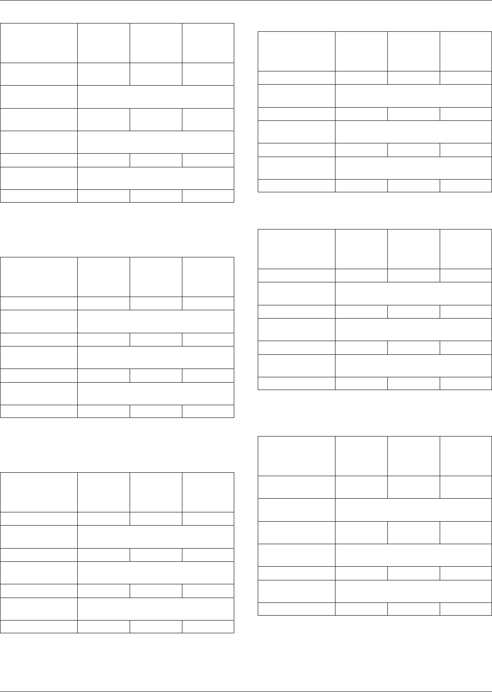
Table 3-4 J Leads (unit: mm)
Lead Part
Minimum
(Least)
Density
Level C
Median
(Nominal)
Density
Level B
Maximum
(Most)
Density
Level A
Heel (to find Z
dim) (J
H
)
0.15 0.35 0.55
Round-off factor
Round off to the nearest two place
even decimal, i.e., 1.00, 1.20, 1.40
Toe (to find G dim)
(J
T
)
-0.30 -0.20 -0.10
Round-off factor
Round off to the nearest two place
even decimal, i.e., 1.00, 1.20, 1.40
Side (J
S
) 0.01 0.03 0.05
Round-off factor
Round off to the nearest two place
decimal, i.e., 1.00, 1.05, 1.10, 1.15
Courtyard excess 0.1 0.25 0.5
Table 3-5 Rectangular or Square-End Components
(Capacitors and Resistors) Equal to or Larger
than 1608 (0603) (unit: mm)
Lead Part
Minimum
(Least)
Density
Level C
Median
(Nominal)
Density
Level B
Maximum
(Most)
Density
Level A
Toe (J
T
) 0.15 0.35 0.55
Round-off factor
Round off to the nearest two place
even decimal, i.e., 1.00, 1.20, 1.40
Heel (J
H
) -0.05 -0.05 -0.05
Round-off factor
Round off to the nearest two place
even decimal, i.e., 1.00, 1.20, 1.40
Side (J
s
) -0.05 0.00 0.05
Round-off factor
Round off to the nearest one place
decimal, i.e., 1.0, 1.1, 1.2, 1.3
Courtyard excess 0.1 0.25 0.5
Table 3-6 Rectangular or Square-End
Components (Capacitors and Resistors)
Smaller than 1608 (0603) (unit: mm)
Lead Part
Minimum
(Least)
Density
Level C
Median
(Nominal)
Density
Level B
Maximum
(Most)
Density
Level A
Toe (J
T
) 0.00 0.10 0.20
Round-off factor
Round off to the nearest two place
decimal, i.e., 1.00, 1.05, 1.10, 1.15
Heel (J
H
) -0.05 -0.05 -0.05
Round-off factor
Round off to the nearest two place
decimal, i.e., 1.00, 1.05, 1.10, 1.15
Side (J
S
) 0.00 0.00 0.05
Round-off factor
Round off to the nearest two place
decimal, i.e., 1.00, 1.05, 1.10, 1.15
Courtyard excess 0.1 0.15 0.20
Table 3-7 Cylindrical End Cap
Terminations (MELF) (unit: mm)x
Lead Part
Minimum
(Least)
Density
Level C
Median
(Nominal)
Density
Level B
Maximum
(Most)
Density
Level A
Toe (J
T
) 0.2 0.4 0.6
Round-off factor
Round off to the nearest two place
even decimal, i.e., 1.00, 1.20, 1.40
Heel (J
H
) 0.02 0.1 0.2
Round-off factor
Round off to the nearest two place
even decimal, i.e., 1.00, 1.20, 1.40
Side (J
S
) 0.01 0.05 0.1
Round-off factor
Round off to the nearest one place
decimal, i.e., 1.0, 1.1, 1.2, 1.3
Courtyard excess 0.1 0.25 0.5
Table 3-8 Bottom Only Terminations (unit: mm)
Lead Part
Minimum
(Least)
Density
Level C
Median
(Nominal)
Density
Level B
Maximum
(Most)
Density
Level A
Toe (J
T
) 0.15 0.35 0.55
Round-off factor
Round off to the nearest two place
even decimal, i.e., 1.00, 1.20, 1.40
Heel (J
H
) 0.25 0.35 0.45
Round-off factor
Round off to the nearest one place
decimal, i.e., 1.0, 1.1, 1.2, 1.3
Side (J
S
) 0.01 0.03 0.08
Round-off factor
Round off to the nearest two place
decimal, i.e., 1.00, 1.05, 1.10, 1.15
Courtyard excess 0.1 0.25 0.5
Table 3-9 Leadless Chip Carrier with
Castellated Terminations (unit: mm)
Lead part
Minimum
(Least)
Density
Level C
Median
(Nominal)
Density
Level B
Maximum
(Most)
Density
Level A
Heel (J
H
) (to find
Z dim)
0.45 0.55 0.65
Round-off factor
Round off to the nearest two place
even decimal, i.e., 1.00, 1.20, 1.40
Toe (J
T
) (to find G
dim)
0.05 0.15 0.25
Round-off factor
Round off to the nearest two place
even decimal, i.e., 1.00, 1.20, 1.40
Side (J
S
) -0.15 -0.05 0.05
Round-off factor
Round off to the nearest two place
decimal, i.e., 1.00, 1.05, 1.10, 1.15
Courtyard excess 0.1 0.25 0.5
February 2005 IPC-7351
13
www.bzfxw.com
Dimensions that have had their tolerance spread reduced
are so indicated in the tables. Parts that are available with
shape characteristics or tolerance limits that fall outside the
recommended norms require land patterns that must be
altered slightly from those presented.
Users of these specialized parts are encouraged to develop
their own land patterns which then become unique to a
specific component vendor part. A dimensioning system
with specific equations has been provided to facilitate
unique land pattern development or enhance process usage.
3.1.5.3 Land Pattern Dimensions Land pattern dimen-
sions are provided in the sectional standards according to
the concepts of maximum material conditions (MMC).
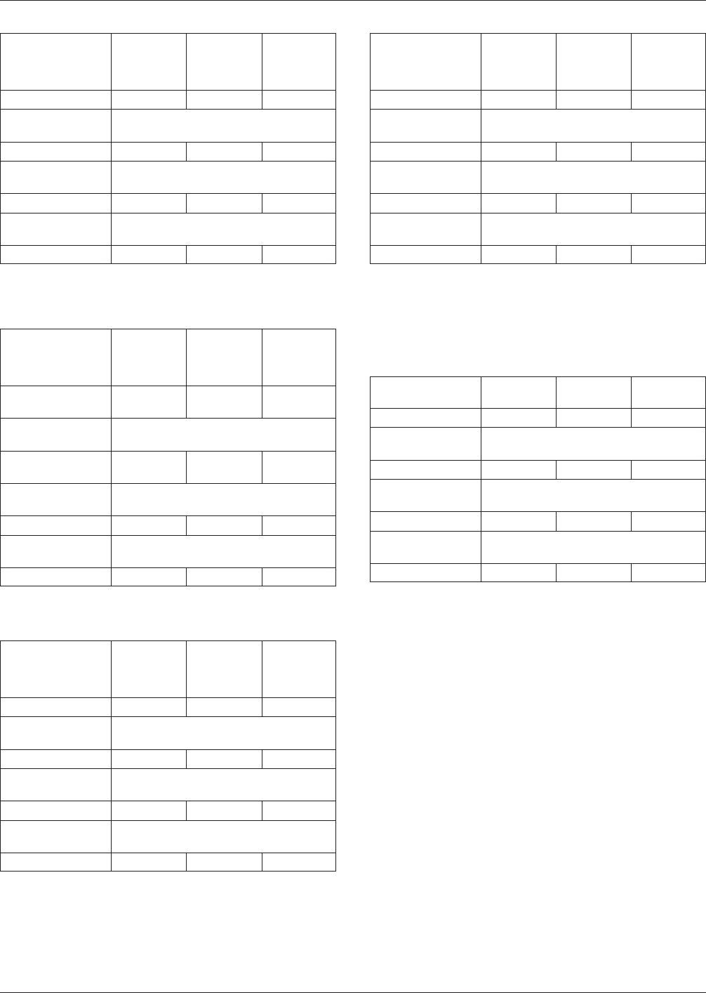
Table 3-10 Butt Joints (unit: mm)
Lead Part
Minimum
(Least)
Density
Level C
Median
(Nominal)
Density
Level B
Maximum
(Most)
Density
Level A
Toe (J
T
) 0.6 0.8 1.0
Round-off factor
Round off to the nearest two place
even decimal, i.e., 1.00, 1.20, 1.40
Heel (J
H
) 0.6 0.8 1.0
Round-off factor
Round off to the nearest one place
decimal, i.e., 1.0, 1.1, 1.2, 1.3
Side (J
S
) 0.1 0.2 0.3
Round-off factor
Round off to the nearest two place
decimal, i.e., 1.00, 1.05, 1.10, 1.15
Courtyard excess 0.2 0.8 1.5
Table 3-11 Inward Flat Ribbon L and Gull-
Wing Leads (Tantalum Capacitors) (unit: mm)
Lead Part
Minimum
(Least)
Density
Level C
Median
(Nominal)
Density
Level B
Maximum
(Most)
Density
Level A
Toe (to find G dim)
(J
T
)
0.07 0.15 0.25
Round-off factor
Round off to the nearest two place
even decimal, i.e., 1.00, 1.20, 1.40
Heel (to find Z
dim) (J
H
)
0.2 0.5 0.8
Round-off factor
Round off to the nearest two place
even decimal, i.e., 1.00, 1.20, 1.40
Side (J
S
) -0.10 -0.05 0.01
Round-off factor
Round off to the nearest one place
decimal, i.e., 1.0, 1.1, 1.2, 1.3
Courtyard excess 0.1 0.25 0.5
Table 3-12 Flat Lug Leads (unit: mm)
Lead Part
Minimum
(Least)
Density
Level C
Median
(Nominal)
Density
Level B
Maximum
(Most)
Density
Level A
Toe (J
T
) 0.15 0.35 0.55
Round-off factor
Round off to the nearest two place
even decimal, i.e., 1.00, 1.20, 1.40
Heel (J
H
) 0.25 0.35 0.45
Round-off factor
Round off to the nearest one place
decimal, i.e., 1.0, 1.1, 1.2, 1.3
Side (J
S
) -0.04 0.01 0.05
Round-off factor
Round off to the nearest two place
decimal, i.e., 1.00, 1.05, 1.10, 1.15
Courtyard excess* 0.1 0.25 0.5
* Depends on thermal requirements.
Table 3-13 Flat, No Lead (unit: mm)
Lead Part
Minimum
(Least)
Density
Level C
Median
(Nominal)
Density
Level B
Maximum
(Most)
Density
Level A
Toe (J
T
) 0.20 0.30 0.40
Round-off factor
Round off to the nearest two place
decimal, i.e., 1.00, 1.05, 1.10, 1.15
Heel (J
H
) 0.00 0.00 0.00
Round-off factor
Round off to the nearest two place
decimal, i.e., 1.00, 1.05, 1.10, 1.15
Side (J
S
) -0.04 -0.04 -0.04
Round-off factor
Round off to the nearest two place
decimal, i.e., 1.00, 1.05, 1.10, 1.15
Courtyard excess 0.1 0.25 0.5
Note: The rationale for the relatively large negative heel stems from the
tolerances for the lead lengths as also being relatively large. In order to
maintain a minimum clearance of 0.20 mm to the thermal tab it becomes
necessary to trim the heel by -0.2 mm. Without a thermal tab the heel can
usually be increased to as much as 0.50 mm.
Table 3-14 Small Outline (SO), No-Lead (unit: mm)
Lead Part
Minimum
Level C
Median
Level B
Maximum
Level A
Toe (J
T
) 0.20 0.30 0.40
Round-off factor
Round off to the nearest two place
decimal, i.e., 1.00, 1.05, 1.10, 1.15
Heel (J
H
) 0.00 0.00 0.00
Round-off factor
Round off to the nearest two place
decimal, i.e., 1.00, 1.05, 1.10, 1.15
Side (J
S
) -0.04 -0.04 -0.04
Round-off factor
Round off to the nearest two place
decimal, i.e., 1.00, 1.05, 1.10, 1.15
Courtyard excess 0.1 0.25 0.5
Note: With a thermal tab the heel can usually be increased to as much as
0.1 mm.
IPC-7351 February 2005
14
标准分享网 www.bzfxw.com 免费下载