IPC-7351-2005_表面贴装焊盘布局设计和标准通用要求.pdf - 第83页
Appendix B (Informative) Abbreviations and Definitions A TE Automated T est Equipment COB Chip-on-Board CTE Coef f icient of Thermal Expansion DIP Dual-in-Line Package DTP Diameter of True Position FTP Fine Pitch T echno…
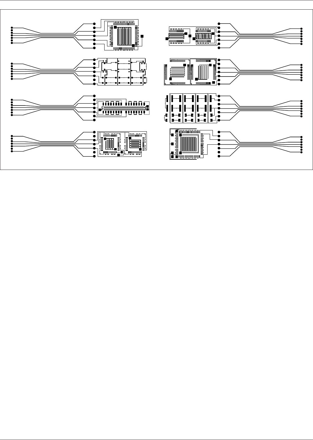
The land patterns are shown in documentation designed to
provide a clear view of the soldering characteristic in such
a way that land geometry is visible, and solder joint evalu-
ation can be achieved. The same in-process validator is
used to check the registration of solder paste prior to reflow
soldering.
IPC/EIA J-STD-001 provides the key variables for meeting
soldering requirements that are necessary for various sur-
face mount parts. Land pattern samples provided around
the periphery of a panel, should be designed to provide
clear visibility of the solder joints shown in these figures.
A.3 Stress Testing Stress testing usually consists of
temperature cycling of the printed board assembly that has
been surface mounted through various extremes. The tem-
perature cycling of the assembly or a coupon may be vari-
ety of cycling exposure (see Table 3-16).
During the cycling processes, daisy-chained plated-through
holes and daisy-chained solder joints are measured during
the initial phase as to their resistance, and then monitored
for increased resistance during the thermal cycling. See
IPC-SM-785 and IPC-9701 for additional information.
IPC-7351-a-02
Figure A-2 Photoimage of IPC-A-49 Test Board for Primary Side
IPC-7351 February 2005
72
标准分享网 www.bzfxw.com 免费下载

Appendix B
(Informative)
Abbreviations and Definitions
ATE Automated Test Equipment
COB Chip-on-Board
CTE Coefficient of Thermal Expansion
DIP Dual-in-Line Package
DTP Diameter of True Position
FTP Fine Pitch Technology
IC Integrated Circuit
ICT In-Circuit Test
IR Infrared
LMC Least Material Condition
MMC Maximum Material Condition
OA Organic Acid
OSP Organic Solderability Protection
PB Printed Board
PTFE Polytetrafluoroethylene
PTH Plated-through Hole
RA Rosin Activated
RFS Regardless of Feature Size
RMA Resin Mildly Activated
RMS Root Mean Square
SA Synthetic-Activated
SFA Standard Fabric Allowances
SIP Single In-Line Package
SMA Synthetic Mildly Activated
SMOBC Solder Mask Over Bare Copper
SMT Surface Mount Technology
SOIC Small Outline Integrated Circuit
THT Through-Hole Technology
February 2005 IPC-7351
73

APPENDIX C
IPC-7351 Land Pattern Viewer
The IPC-7351 Land Pattern Viewer, hereafter referred to as
the IPC-7351 LP Viewer, is a shareware program that
allows users to view component and land pattern dimen-
sional data in tabular form as well as graphical images that
illustrate how a component is attached to the land pattern
on the board. The IPC-7351 LP Viewer is provided on a
CD-ROM that is included with the IPC-7351 standard.
Updated versions of the program, including dimensional
data for new component families, can be downloaded for
free from www.ipc.org under the ‘‘PCB Tools and Calcu-
lators’’ link.
C.1 Software Installation The IPC-7351 LP Viewer
comes on CD-ROM in a zipped file format. The zip file
contains important text files on the usage of the shareware
program as well as installation requirements. Microsoft
.NET Framework is required for the IPC-7351 LP Viewer
to run properly. If you have determined that you do not
have this component, the installation requirement text file
details how to obtain this software. Once you have con-
firmed that your system has Microsoft .NET Framework,
you can select the executable IPC-7351 LP Viewer file to
begin the installation process. See the Users Guide within
the IPC-7351 LP Viewer for detailed instructions on the
download of .NET Framework.
Note: A special file is required for the eventual build of
user preferences; this file has the extension [.dat]. The IPC-
7351 LP Viewer program installation does not initially
include a [.dat] file and therefore one is created automati-
cally the first time you run the program. When starting the
program for the first time, the User will be prompted by a
message that states a .DAT file does not exist and that one
is being created. A second message will be displayed con-
firming that the file has been created.
C.2 Software Usage Once installed, select the ‘‘Users
Guide’’ tool bar button located on the main interface screen
for the IPC-7351 LP Viewer. This .pdf document helps in
familiarizing the user with the Viewer by providing
detailed information on the following:
• Software Installation
• Setting up User Preferences
• Operating the Search Library Menu
• Updating Parts Library Files
C.3 Software Updates The IPC-7351 LP Viewer relies
on library files for component and land pattern dimensional
data. The extension for the library files is [.p]. These .p
files provide the raw dimensional data necessary for the
software to display components and land patterns in
graphical forum.
.p files also contain parts attributes. Attributes hold vital
statistical and descriptive data that every land pattern needs
so other users can quickly identify the component charac-
teristics. Attributes help organize data used to search for
existing library parts. Detailed descriptions of how to uti-
lize attributes can be found by selecting the ‘‘Users Guide’’
tool bar button located on the main interface screen for the
IPC-7351 LP Viewer.
As new component families are standardized by the indus-
try, new .p library files will be made available to users of
the IPC-7351 LP Viewer. These updated .p files can be
downloaded for free from www.ipc.org under the ‘‘PCB
Tools and Calculators’’ link.
C.4 Software Upgrades The IPC-7351 LP Viewer is a
shareware program that allows users to search and display
existing land patterns for standardized component families.
The Viewer is supported by additional software tools that
allow for the calculation of new land patterns as well as the
creation of new part libraries that stores new component
and land pattern data. Information on these enhanced soft-
ware tools is available at www.ipc.org under the ‘‘PCB
Tools and Calculators’’ link.
IPC-7351 February 2005
74
标准分享网 www.bzfxw.com 免费下载