IPC-7351-2005_表面贴装焊盘布局设计和标准通用要求.pdf - 第30页
www.bzfxw.com See IPC-SM-785 and IPC-9701 for details regarding com- ponent and assembly testing. 3.4 Design Rules The printed board design principles recommended in this standard consider current test and manufacturing …

www.bzfxw.com
Table 3-16 Product Categories and Worst-Case Use Environments for Surface Mounted Electronics (For Reference Only)
Product Category
(Typical Application)
Temperature, °C / °F
(1)
Worst-Case Use Environment
Storage Operation
Tmin
(2)
°C/°F
Tmax
(2)
°C/°F
∆T
(3)
°C/°F
t
D
(4)
hrs Cycles/year
Typical years
of Service
Approx. Accept.
Failure Risk, %
Consumer -40/85 0/55 0/32 60/140 35/63 12 365 1-3 1
Computers and Peripherals -40/85 0/55 0/32 60/140 20/36 2 1460 5 0.1
Telecomm -40/85 -40/85 -40/-40 85/185 35/63 12 365 7-20 0.01
Commercial Aircraft -40/85 -40/85 -55/-67 95/203 20/36 12 365 20 0.001
Industrial and Automotive -
Passenger Compartment
-55/150 -40/85 -55/-67 95/203 20/36
&40/72
&60/108
&80/144
12
12
12
12
185
100
60
20
10-15 0.1
Military
(ground and shipboard)
-40/85 -40/85 -55/-67 95/203 40/72
&60/108
12
12
100
265
10-20 0.1
Space
leo
geo
-40/85 -40/85
-55/-67 95/203
3/5.4
to 100/180
1
12
8760
365
5-30 0.001
Military Aircraft
a
b
c
Maintenance
-55/125 -40/85
-55/-67 125/257 40/72
60/108
80/144
2
2
2
100
100
65
10-20 0.01
&20/36 1 120
Automotive
(under hood)
-55/150 -40/125 -55/-67 125/257 60/108
&100/180
&140/252
1
1
2
1000
300
40
10-15 0.1
& = in addition
1. All categories may be exposed to a process temperature range of 18°C to 260°C [64.4°F to 500°F].
2. Tmin and Tmax are the operational (test) minimum and maximum temperatures, respectively, and do not determine the maximum ∆T.
3. ∆T represents the maximum temperature swing, but does not include power dissipation effects; for power dissipation calculate ∆T; power dissipation can make pure temperature cycling accelerated testing
significantly inaccurate. It should be noted that the temperature range, ∆T, is not the difference between Tmin and Tmax ; ∆T is typically significantly less.
4. The dwell time, t
D
, is the time available for the creep of the solder joints during each temperature half-cycle.
February 2005 IPC-7351
19

www.bzfxw.com
See IPC-SM-785 and IPC-9701 for details regarding com-
ponent and assembly testing.
3.4 Design Rules The printed board design principles
recommended in this standard consider current test and
manufacturing capabilities. Exceeding the limitation of
these capabilities requires concurrence of all participants in
the process including manufacturing, engineering and test
technology. Involving test and manufacturing early in the
design helps to move a quality product quickly into pro-
duction.
Manufacturing engineering should be consulted regarding
any components outside the scope of this document.
3.4.1 Component Spacing
3.4.1.1 Component Considerations
The land pattern
design and component spacing affect the reliability, manu-
facturability, testability and repairability of surface mount
assemblies. A minimum inter-package spacing is required
to satisfy all these manufacturing requirements. Maximum
inter-package spacing is limited by several factors, such as
available board space, equipment, weight considerations,
and circuit operating speed requirements. Some designs
require that surface mount components be positioned as
close to one another as possible.
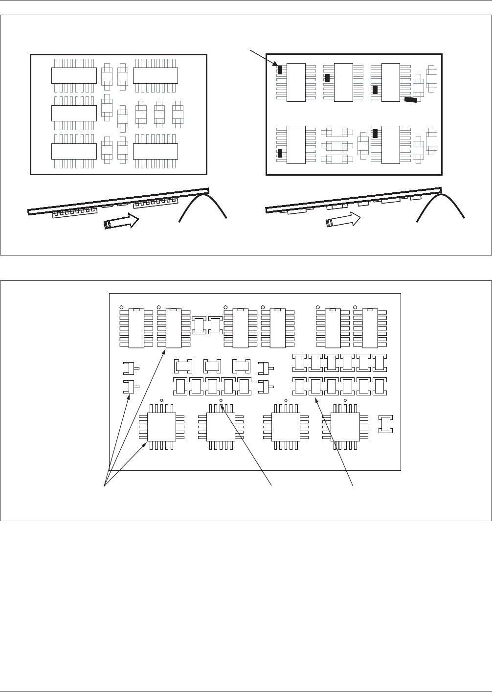
3.4.1.2 Wave Solder Component Orientation On any
printed board assembly where surface mount devices are to
be wave soldered, the orientation of devices in respect to
the solder wave can contribute to excessive solder process
defects. The preferred orientation compared in Figure 3-6
optimises the solder process, minimizing solder bridging
on the trailing or shadowed contacts as the assembly exits
the solder wave. All polarized surface mount components
should be placed in the same orientation when possible.
The following additional conditions apply:
a) All passive components should be parallel to each
other.
b) The longer axis of SOICs and the longer axis of passive
components shall be perpendicular to each other.
c) The long axis of passive components shall be perpen-
dicular to the direction of travel of the board along the
conveyer of the wave solder machine.
3.4.1.3 Component Placement Similar types of compo-
nents should be aligned on the board in the same orienta-
tion for ease of component placement, inspection, and sol-
dering. Also, similar component types should be grouped
together whenever possible, with the net list or connectiv-
ity and circuit performance requirements ultimately driving
the placements. In memory boards, for example, all of the
memory chips are placed in a clearly defined matrix with
pin one orientation in the same direction for all compo-
nents. This is a good design practice to carry out on logic
designs where there are many similar component types
with different logic functions in each package. On the other
hand, analogue designs often require a large variety of
component types making it understandably difficult to
group similar components together. Regardless of whether
the design is memory, general logic, or analog, it is recom-
mended (when possible) that the orientation of pin 1 on all
IC components is the same, provided that product perfor-
mance or function is not compromised.
3.4.1.4 Grid-Based Component Positioning SMT com-
ponent placement is generally more complex than PIH
printed boards for two reasons: higher component densi-
ties, and the ability to put components on both sides of the
board. In high-density SMT designs the spacing between
lands of different components are often less than 0.2 mm.
Grid-based SMT device placement may not be practical
due to the large variety of component shapes.
Two effects created by random component placement are a
loss of uniform grid-based test node accessibility and a loss
of logical, predictable routing channels on all layers (pos-
sibly driving layer counts). In addition, the accepted inter-
national grid identified in IPC-1902 states that for new
designs the grid should be 0.5 mm, with a further subdivi-
sion being 0.05 mm. One solution to the problem is to
build CAD libraries with all component lands connected to
vias on 0.5 mm centers (or greater, based on design) to be
used for testing, routing, and rework ports.
It is easier to process a printed board (PB) that has uniform
component center-point spacing cross the board in both
directions (see Figure 3-7).
3.4.2 Single- and Double-Sided Board Assembly The
term single-sided board assembly refers to components
mounted on one side, and the term double-sided refers to
components mounted on both sides of the board. The
double-sided board assembly may require additional solder
and assembly process steps and can increase manufacturing
cost. Designers should concentrate on locating all compo-
nents on the primary side of the board whenever possible.
3.4.2.1 Solder Paste Stencil The solder stencil is the
primary vehicle by which solder paste is applied to the
IPC-7351 February 2005
20
标准分享网 www.bzfxw.com 免费下载
www.bzfxw.com
SMT printed board. With it, the exact location and volume
of solder paste deposition is precisely controlled. The art-
work for developing the stencil is the component mounting
lands from the outer layers of the board with all other cir-
cuitry deleted. The information provided for the openings
in the stencil is usually indicated as being the same size as
the lands on the board for all components. This information
(or data) may be selectively modified by the printed board
assembler or process engineer who will define the specific
adjustments required to meet specific solder volume
requirements (see IPC 7525).
The optimum stencil thickness is determined by evaluating
the solder paste requirements for all the components to be
reflow soldered. This should be based on study of the mini-
mum and target requirements for SMT solder joints given
in IPC/EIA-J-STD-001.
Ideally, the volume deposited should be the total amount
required to achieve the ‘‘target’’ solder joint condition (see
IPC-A-610), less the solder already available on the land
and termination or lead (the latter can together amount to
10% to 20% of the total and should not be ignored). In
IPC-7351-3-06
Figure 3-6 Component Orientation for Wave-Solder Applications
Preferred Orientation
Defect Prone Orientation
Solder
bridging
Solder
Wave
Solder
Wave
IPC-7351-3-07
Figure 3-7 Alignment of Similar Components
Consistent
Orientation
Pin 1 I.D. Uniform
Spacing
February 2005 IPC-7351
21