IPC-7351-2005_表面贴装焊盘布局设计和标准通用要求.pdf - 第48页
6.1 General Considerations Printed board structures vary from basic printed wiring boards to very sophisticated supporting-core structures. However, some selection crite- ria are common to all structures. T o aid in the …

Table 6-1 Printed Board Structure Comparison
Type Major Advantages Major Disadvantages Comments
Organic Base Substrate
Epoxy fiberglass Substrate size, weight, rework-
able, dielectric properties, con-
ventional board processing.
Thermal conductivity, X, Y and Z
axis CTE.
Because of its high X-Y plane
CTE, it should be limited to
environments and applications
with small changes in tempera-
tures and/or small packages.
Polyimide fiberglass Same as epoxy fiberglass plus
high temperatures X-Y axis
CTE, substrate size, weight,
reworkable, dielectric properties,
high T
g
.
Thermal conductivity, Z-axis
CTE, moisture absorption.
Same as epoxy fiberglass.
Epoxy aramid fiber Same as epoxy fiberglass,
X-axis CTE, substrate size,
lightest weight, reworkable,
dielectric properties.
Thermal conductivity, Z-axis
CTE, resin microcracking, Z
axis CTE, water absorption.
Volume fraction of fiber can be
controlled to tailor X-Y CTE.
Resin selection critical to
reducing resin micro-cracks.
Polyimide aramid fiber Same as epoxy aramid fiber,
X-axis CTE, substrate size,
weight, reworkable, dielectric
properties.
Thermal conductivity, Z-axis
CTE, resin microcracking, water
absorption.
Same as epoxy aramid fiber.
Polyimide quartz (fused
silica)
Same as polyimide aramid fiber,
X-Y axis CTE, substrate size,
weight, reworkable, dielectric
properties.
Thermal conductivity, Z-axis
CTE, drilling, availability, cost,
low resin content required.
Volume fraction of fiber can
be controlled to tailor X-Y CTE,
drill wear-out higher than with
fiberglass.
Fiberglass/aramid
composite fiber
Same as polyimide aramid fiber,
no surface microcracks, Z axis
CTE, substrate size, weight,
reworkable, dielectric properties.
Thermal conductivity, X and Y
axis CTE, water absorption,
process solution entrapment.
Resin microcracks are confined
to internal layers and cannot
damage external circuitry.
Fiberglass/PTFE®
laminates
Dielectric constant, high
temperature.
Same as epoxy fiberglass, low-
temperature stability, thermal
conductivity, X and Y axis CTE.
Suitable for high-speed logic
applications. Same as epoxy
fiberglass.
Flexible dielectric Light weight, minimal concern to
CTE, configuration flexibility.
Size, cost, Z-axis expansion. Rigid-flexible boards offer
trade-off compromises.
Thermoplastic 3-D configurations, low high-
volume cost.
High injection-moulding setup
costs.
Relatively new for these
applications.
Nonorganic Base
Alumina (ceramic) CTE, thermal conductivity,
conventional thick film or thin
film processing, integrated
resistors.
Substrate size, rework limita-
tions, weight, cost, brittle,
dielectric constant.
Most widely used for hybrid
circuit technology.
Supporting Plane
Printed board bonded to
plane support (metal or
nonmetal)
Substrate size, reworkability,
dielectric properties, conven-
tional board processing, X-Y
axis CTE, stiffness, shielding,
cooling.
Weight. The thickness/CTE of the metal
core can be varied along with
the board thickness, to tailor the
overall CTE of the composite.
Sequential processed
board with supporting
plane core
Same as board bonded to
supporting plane.
Weight. Same as board bonded to
supporting plane
Discrete wire High-speed interconnections,
good thermal and electrical
features.
Licensed process, requires
special equipment.
Same as board bonded to low-
expansion metal support plane.
Constraining Core
Porcelainized copper-clad
invar
Same as alumina. Reworkability, compatible thick
film materials.
Thick film materials are still
under development.
Printed board bonded
with constraining metal
core
Same as board bonded to low
expansion metal cores, stiff-
ness, thermal conductivity, low
weight.
Cost, microcracking. The thickness of the graphite
and board can be varied to
tailor the overall CTE of the
composite.
Compliant layer sructures Substrate size, dielectric
properties, X-Y axis, CTE.
Z-axis CTE, thermal
conductivity.
Compliant layer absorbs
difference in CTE between
ceramic package and substrate.
February 2005 IPC-7351
37
6.1 General Considerations Printed board structures
vary from basic printed wiring boards to very sophisticated
supporting-core structures. However, some selection crite-
ria are common to all structures. To aid in the selection
process, Table 6-2 lists design parameters and material
properties which affect system performance, regardless of
PCB type. Also, Table 6-3 lists the properties of the mate-
rials most common for these applications.
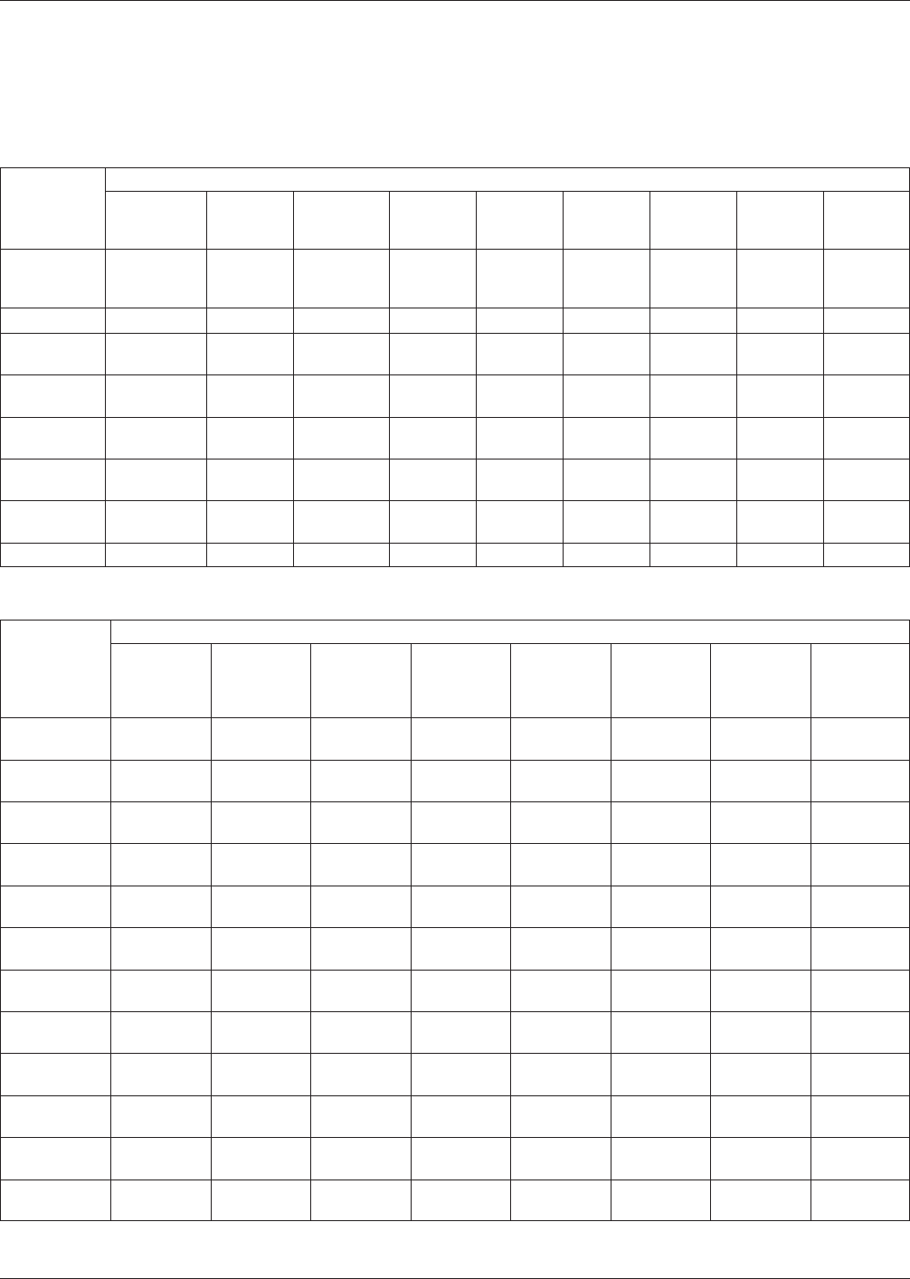
Table 6-2 PCB Structure Selection Considerations
Design
Parameters
Material Properties
Transition
Temperatures
Coefficient
of Thermal
Expansion
Thermal
Conductivity
Tensile
Modulus
Flexural
Modulus
Dielectric
Constant
Volume
Resistivity
Surface
Resistivity
Moisture
Absorption
Temperatures
and power
cycling
XXXX
Vibration X X
Mechanical
shock
XX
Temperatures
and humidity
X X XXXX
Power
density
XX
Chip carrier
size
XX
Circuit
density
XXX
Circuit speed XXX
Table 6-3 PCB Structure Material Properties
Material
Material Properties
Glass
Transition
Temperature
XY
Coefficient
of Thermal
Expansion
Thermal
Conductivity
XY Tensile
Modulus
Dielectric
Constant
Volume
Resistivity
Surface
Resistivity
Moisture
Absorption
Unit of
Measure
°C PPM/°C
(Note 4)
W/M°C PSI x 10
-6
At 1 MHz Ohms/cm Ohms Percent
Epoxy
fiberglass
125 13-18 0.16 2.5 4.8 10
12
10
13
0.10
Polyimide
fiberglass
250 12-16 0.35 2.8 4.8 10
14
10
13
0.35
Epoxy aramid
fiber
125 6-8 0.12 4.4 3.9 10
18
10
16
0.85
Polyimide
aramid fiber
250 3-7 0.15 4.0 3.6 10
12
10
12
1.50
Polyimide
quartz
250 6-8 0.30 4.0 10
9
10
8
0.50
Fiberglass/
Teflon®
75 20 0.26 0.2 2.3 10
10
10
11
1.10
Thermoplastic
resin
190 25-30 3-4 10
17
10
13
N/A
Alumina-
beryllia
N/A 5-7 21.0 44.0 8.0 10
14
Aluminum
(6061 T-6)
N/A 23.6 200 10 N/A 106 N/A
Copper
(CDA101)
N/A 17.3 400 17 N/A 10
6
Copper-clad
Invar
N/A 3-6 150XY/20Z 17-22 N/A 10
8
N/A
IPC-7351 February 2005
38
标准分享网 www.bzfxw.com 免费下载

6.1.1 Categories In general, a PCB structure will fit into
one of four basic categories of construction: organic base
material, nonorganic base material, supporting plane, and
constraining core.
6.1.2 Thermal Expansion Mismatch A primary concern
when using low expansion surface mount parts is the ther-
mal expansion mismatch between the leadless part and the
PCB structure. This mismatch will fracture solder joint
interconnections if the assembly is subjected to thermal
shock, thermal cycling, power cycling and high operating
temperatures. The number of fatigue cycles before solder
joint failure depends on the thermal expansion mismatch
between the part and the PCB structure, the temperature
range over which the assembly must operate, the solder
joint thickness, the size of the part and the power cycling.
For example, power cycling may cause an undesirable ther-
mal expansion mismatch if a significant temperature differ-
ence exists between a device or package and the PB struc-
ture.
6.2 Organic-Base Material Organic-base materials work
best with leaded chip carriers. With leadless chip carriers
and some BGA packaging, the thermal expansion mis-
match between package and substrate can cause problems.
Also, flatness, rigidity, and thermal conductivity require-
ments may limit their use. Finally, attention should be paid
to package size, I/O count, thermal cycling stability, maxi-
mum operating temperature and solder joint compliance.
6.3 Nonorganic Base Materials Nonorganic ceramic
base materials typically used with thick- or thin-film tech-
nology, although more costly, are suited for leaded and
leadless chip carrier designs. Suppliers can incorporate
thick- or thin-film resistors directly on the ceramic struc-
ture and buried capacitor layers that increase density and
improve reliability. However, repairability of the PCB
structure is limited. Ceramic materials, usually alumina,
appear ideal for PCB structure with leadless ceramic chip
carriers because of their relatively high thermal conductiv-
ity. Unfortunately, the structure is limited to approximately
100 mm square. Ceramic PCB structures have three pri-
mary applications: ceramic hybrid circuits, ceramic multi-
chip modules (MCM-L) and ceramic printed boards.
6.4 Alternative PCB Structures
6.4.1 Supporting-Plane PCB Structures
Supporting
metallic or nonmetallic planes can be used with conven-
tional printed boards or with custom processing to enhance
PCB properties. Depending on the results desired, the sup-
porting plane can be electrically functional or not and can
also serve as a structure stiffener, heatsink and/or CTE con-
straint.
6.4.2 High-Density PCB Technology High-density,
sequentially processed, multilayer PCB structures are avail-
able in a wide variety of organic dielectrics. Using thinner
copper foils for fabrication the board manufacturer can pro-
vide very narrow conductor and spacing features and by
implementing smaller mechanical drills, laser ablation,
photo-lithography or plasma processes, smaller blind
and/or buried vias can be provided for layer-to-layer inter-
connections.
The major advantage of this system is that the vias can be
as small as 0.10 mm [0.00394 in] or less and conductor
widths can range from below 0.12 mm [0.00472 in] for
high interconnection density. Thus, some applications can
be satisfied with fewer signal layers while providing addi-
tional layers for power and ground. Refer to IPC-2226 for
more detailed design guidelines for high density PCB.
6.4.3 Constraining Core Structures As with supporting
plane, one or more supporting metallic or nonmetallic
planes can serve as a stiffener, heatsink, and/or CTE con-
straint in constraining core structures.
6.4.4 Porcelainized Metal (Metal Core) Structures An
integral core of low-expansion metal (for example, copper-
clad Invar) can reduce the CTE of porcelainized metal
structures so that it closely matches the CTE of the ceramic
chip carrier. Also, the structure size is virtually unlimited.
However, the low melting point of the porcelain requires
low-firing-temperature conductor, dielectric and resistor
inks.
7 ASSEMBLY CONSIDERATION FOR SURFACE MOUNT
TECHNOLOGY (SMT)
The smaller size of surface mount components and the
option of mounting them on one or both sides of the pack-
aging and interconnecting structure reduces board real
estate significantly. The type of SMT assembly is basically
determined by the type of surface mount components to be
used; see 7.1 for a description of types and classes.
7.1 SMT Assembly Process Sequence The SMT assem-
blies are soldered by reflow (infrared, hot air convection,
laser, conduction, vapor phase, and/or wave soldering pro-
cesses) depending upon the mix of surface mount and
through-hole mount components. The process sequence for
one-sided SMT is shown in Figure 7-1. Solder paste is
applied, components are placed, the assembly is reflow sol-
dered and cleaned. For two-sided SMT assemblies, the
board is turned over and the process sequence just
described is repeated. The assembly process for two-sided
SMT is simply a sequential combination of SMT processes,
however, component weight vs. surface tension should be
calculated to determine if heavy components will require
additional reinforcement prior to the second reflow solder-
ing process.
February 2005 IPC-7351
39