IPC-7351-2005_表面贴装焊盘布局设计和标准通用要求.pdf - 第63页
There are several lead pitches within the family from 1.27 mm down to 0.30 mm. High lead-count packages are available in this family that accommodate complex, high lead-count chips. The four sided gull-wing families of p…
9.5.3 Resistance to Soldering Parts should be capable
of withstanding ten cycles through a standard reflow sys-
tem operating at 215 °C [419 °F]. Each cycle shall consist
of 60 seconds exposure at 215 °C [419 °F]. Parts must also
be capable of withstanding a minimum of 10 seconds
immersion in molten solder at 260 °C [500 °F]. See IPC/
JEDEC J-STD-020 for appropriate reflow cycles and pro-
files when using lead free solders.
10 IPC-7354 J-LEADED COMPONENTS, TWO SIDES
The two-sided J lead family is a small outline family iden-
tified by the dimension of the body size in inches. For
example, the SOJ/300 has a body size of 0.300 inches or
7.63 mm, the SOJ/350 has a body size of 0.350 inches or
8.88 mm, the SOJ/400 has a body size of 0.400 inches or
10.12 mm, and the SOJ/450 has a body size of 0.450
inches or 11.38 mm. Package lead counts range from 14 to
28 pins. IPC-7354 SOJ component outlines are derived
from outlines MO-061, MO-063, MO-065, MO-077,
MO-088, MS-027, and MS-091 within JEDEC Publication
95.
End terminations should be solder coated with a tin/lead
alloy or a lead free equivalent. The solder should contain
between 58 to 68% tin. Solder may be applied to the ter-
mination by hot dipping or by plating from solution. Plated
solder terminations should be subjected to a postplating
reflow operation to fuse the solder. The tin/lead finish
should be at least 0.0075 mm [0.0003 in] thick.
The termination shall be symmetrical, and shall not have
nodules lumps, protrusions, etc., that compromise the sym-
metry or dimensional tolerances of the part. The end termi-
nation shall cover the ends of the components, and shall
extend out to the top and bottom of the component.
Solder finish applied over precious metal electrodes shall
have a diffusion-barrier layer between the electrode metal-
lization and the solder finish. The barrier layer should be
nickel or an equivalent diffusion barrier, and should be at
least 0.00125 mm [0.00005 in] thick.
For lead free finishes a combination of tin, silver and cop-
per is the prevalent replacement for the tin/lead finish. Sol-
derability testing should be applied per IPC-J-STD-002 to
determine attachment capability of the applicable compo-
nent type.
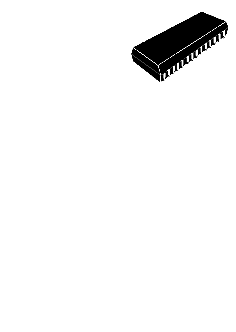
10.1 Basic Construction See Figure 10-1. The small-
outline ‘‘J’’ (SOJ) package has metallic ‘‘J’’ leads on two
sides, similar to a DIP. The lead configuration, like the let-
ter J, extends out the side of the plastic body package and
bends under the package forming a J bend. The point of
contact of the lead to the land pattern is at the apex of the
J bend and is the basis for the span of the land pattern.
The leads must be coplanar within 0.1 mm. That is, when
the component is placed on a flat surface, no lead may be
more than 0.1 mm off the flat surface.
The SOJ package takes advantage of chips having parallel
address or data line layouts. For example, memory IC’s are
often used in multiples, and buss lines connect to the same
pin on each chip. Memory chips in SOJ packages can be
placed close to one another because of the parallel pin lay-
out and the use of ‘‘J’’ leads. With high capacity memory
systems, the space savings can be significant.
10.2 Marking The SOJ family of parts is generally
marked with manufacturers’ part numbers, manufacturers’
name or symbol, and a pin 1 indicator. Some parts may
have a pin 1 feature in the case shape instead of pin 1
marking. Additional markings may include date code/
manufacturing lot and/or manufacturing location.
10.3 Carrier Package Format Components may be pro-
vided in tube or tape packaging. Tape is preferred for best
handling and high volume applications. Bulk packaging is
not acceptable because of lead coplanarity requirements
required for placement and soldering. EIA-481 provides
details on tape requirements.
10.4 Process Considerations J lead packages are nor-
mally processed using standard solder reflow processes.
Parts should be capable of withstanding 10 cycles through
a standard reflow system operating at 215°C [419 °F]. Each
cycle shall consist of 60 seconds exposure at 215°C
[419 °F]. See IPC/JEDEC J-STD-020 for appropriate
reflow cycles and profiles when using lead free solders.
11 IPC-7355 GULL-WING LEADED COMPONENTS,
FOUR SIDES
The four-sided gull-wing family is characterized by gull
wing leads on four sides of a square or rectangular pack-
age. The family includes both molded plastic and ceramic
case styles. The acronyms PQFP (Plastic Quad Flat Pack),
BQFP (Bump Quad Flat Pack), SQFP (Shrink Quad Flat
Pack), QFPR (Quad Flat Pack, Rectangular) and CQFP
(Ceramic Quad Flat Pack) are also used to describe the
family.
IPC-7351-10-01
Figure 10-1 SOJ Construction
IPC-7351 February 2005
52
标准分享网 www.bzfxw.com 免费下载
There are several lead pitches within the family from
1.27 mm down to 0.30 mm. High lead-count packages are
available in this family that accommodate complex, high
lead-count chips.
The four sided gull-wing families of parts are generally
marked with manufacturer part numbers, manufacturer
name or symbol, and a pin 1 indicator. Some parts may
have a pin 1 feature in the case shape instead of pin 1
marking. Additional markings may include date code/
manufacturing lot and/or manufacturing location.
End terminations should be solder coated with a tin/lead
alloy or a lead free equivalent. The solder should contain
between 58 to 68% tin. Solder may be applied to the ter-
mination by hot dipping or by plating from solution. Plated
solder terminations should be subjected to a postplating
reflow operation to fuse the solder. The tin/lead finish
should be at least 0.0075 mm [0.0003 in] thick.
The termination shall be symmetrical, and shall not have
nodules lumps, protrusions, etc., that compromise the sym-
metry or dimensional tolerances of the part. The end termi-
nation shall cover the ends of the components, and shall
extend out to the top and bottom of the component.
Solder finish applied over precious metal electrodes shall
have a diffusion-barrier layer between the electrode metal-
lization and the solder finish. The barrier layer should be
nickel or an equivalent diffusion barrier, and should be at
least 0.00125 mm [0.00005 in] thick.
For lead free finishes a combination of tin, silver and cop-
per is the prevalent replacement for the tin/lead finish. Sol-
derability testing should be applied per IPC-J-STD-002 to
determine attachment capability of the applicable compo-
nent type.
Four-sided gull-wing families are usually processed using
standard solder reflow processes. Parts should be capable
of withstanding ten cycles through a standard reflow sys-
tem operating at 215 °C [419 °F]. Each cycle shall consist
of 60 seconds exposure at 215 °C [419 °F]. High lead-
count fine pitch parts may require special processing out-
side the normal pick/place and reflow manufacturing opera-
tions. See IPC/JEDEC J-STD-020 for appropriate reflow
cycles and profiles when using lead free solders.
All parts shall be marked with a part number and an index
area. The index area shall identify the location of pin 1.
Note: Four sided gull-wing packages are normally pro-
cessed by solder reflow operations. High lead-count fine
pitch parts may require special processing outside the nor-
mal pick/place and reflow manufacturing operations.
Separate pick/place, excise, and reflow processes are some-
times used as an alternate to normal SMT processes.
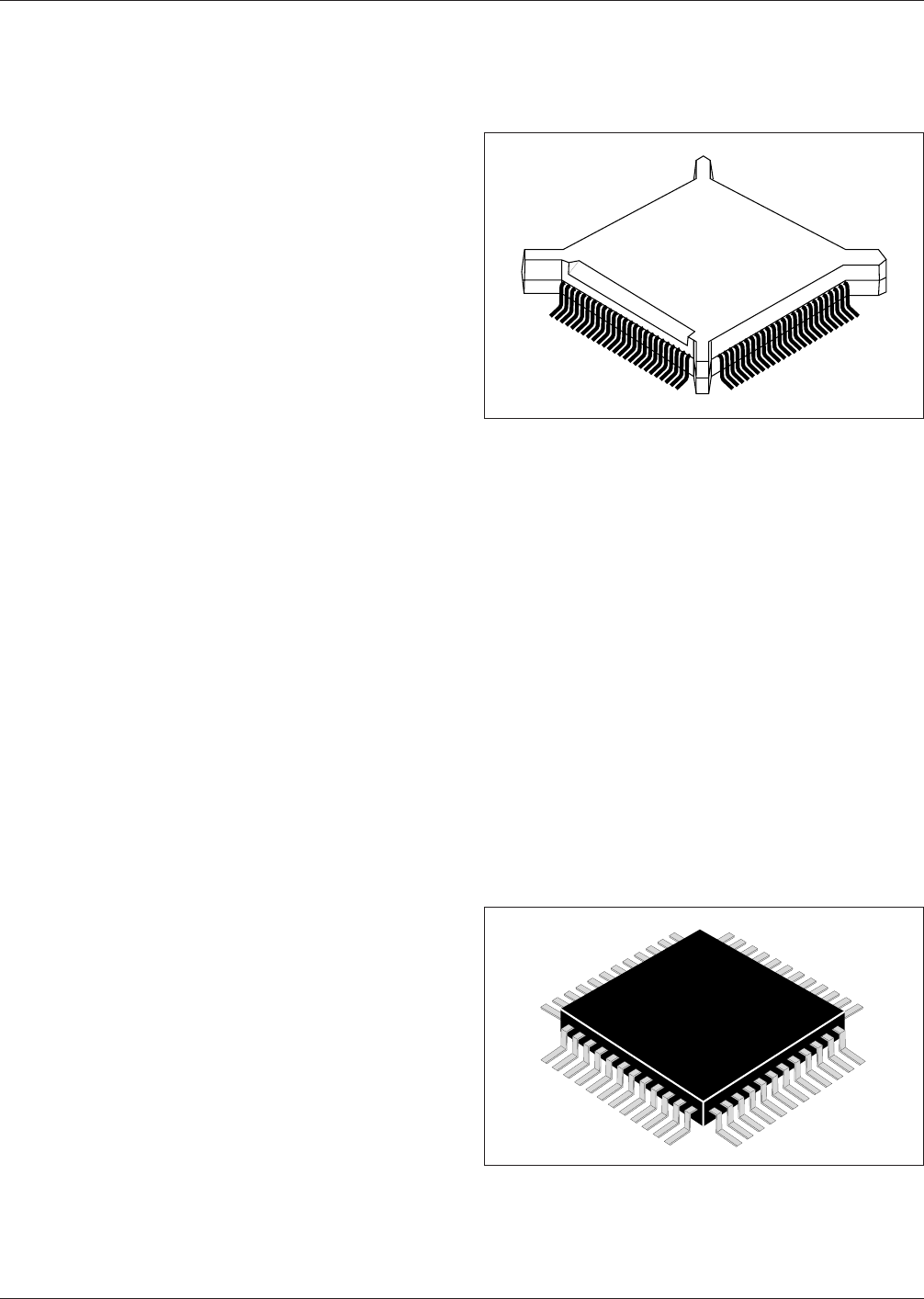
11.1 BQFP (PQFP) See Figure 11-1. BQFPs have leads
on a 0.635 mm pitch. IPC-7355 BQFP component outlines
are derived from outlines MO-069 and MO-086 within
JEDEC Publication 95.
11.1.1 Carrier Package Format The carrier package for-
mat for BQFPs is the tube format; however, packaging
trays provide the best handling capability.
11.2 SQFP/QFP The shrink quad flat pack (SQFP) has
been developed for applications requiring low height and
high density. The SQFP, along with the TSOP components,
are frequently used in memory card applications. The
square SQFP/QFP family has leads on a 0.80 mm,
0.65 mm, 0.63 mm, 0.50 mm, 0.40 mm, or 0.30 mm pitch.
IPC-7355 SQFP/QFP component outlines are derived from
outline MO-108 within JEDEC Publication 95.
Two different pin counts are allowed for each package and
the component will still meet the standard (e.g., a 5x5
package with a 0.3 mm pitch can have either 56 or 48 pins,
and still meet EIAJ-7404-1). QFPs are also square and
come in larger pitches (see Figure 11-2).
11.2.1 Carrier Package Format The carrier package for-
mat for flatpacks may be tube format; but, in most
instances, flatpacks are delivered in a carrier tray.
IPC-7351-11-01
Figure 11-1 BQFP Construction
IPC-7351-11-02
Figure 11-2 SQFP and QFP Construction
February 2005 IPC-7351
53
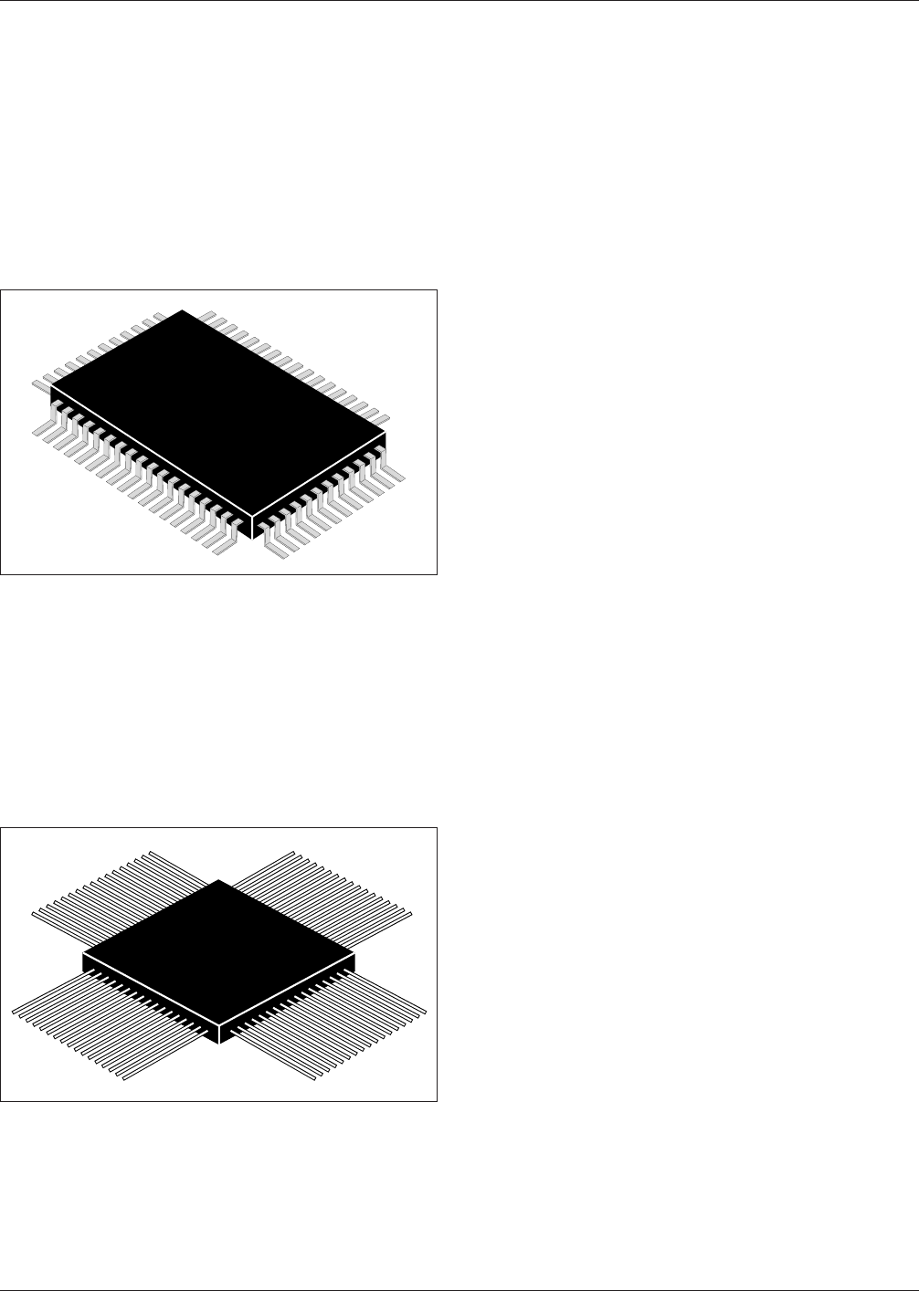
11.3 QFPR The quad flat pack, rectangular (QFPR) has
been developed for applications requiring low height and
high density. The QFPR, along with the TSOP components,
are frequently used in memory card applications. The
QFPR family has leads on a 0.80 mm, 0.60 mm, 0.50 mm,
0.40 mm, or 0.30 mm pitch. IPC-7355 QFPR component
outlines are derived from outline MO-108 within JEDEC
Publication 95 (see Figure 11-3). Two different pin counts
are allowed for each package and the component will still
meet the standard (e.g., a 5x5 package with a 0.3 mm pitch
can have either 56 or 48 pins, and still meet EIAJ-7404-1).
11.3.1 Carrier Package Format The carrier package for-
mat for flat packs may be tube format; but, in most
instances, flat packs are delivered in a carrier tray.
11.4 CQFP See Figure 11-4 for ceramic quad flat pack
(CQFP) construction. Leaded ceramic chip carriers are
typically supplied with an open cavity for chip placement.
Ceramic or metal lids are soldered, epoxied, or attached
with glass frit around the cavity to provide a hermetic seal.
An exception to this construction is the JEDEC standard
outline MS-044, which has the chip bonded to a lead
frame, which is then sealed between two ceramic bodies
with glass frit, similar to CERDIP fabrication. The ceramic
packages are available in 28- through 196-lead configura-
tions, with 1.27 mm, 0.80 mm, and 0.63 mm center spac-
ing. Aside from the MS-044 exception, IPC-7355 CQFP
component outlines are derived from outlines MO-084,
MO-104 and MO-114 within JEDEC Publication 95.
Preleaded ceramic chip carriers typically have copper alloy
or Kovar leads that are attached by the manufacturer. Leads
are typically bonded to metallization on the top surface of
the chip carrier. However, leads can be attached to the
package castellations as well. Brazing or thermo-
compression bonding is usually the attachment means. Pre-
leaded packages using lead-frame construction are also
available. These chip carriers have ceramic bodies with two
opposing halves which mate above and below a lead frame
to which the chip has been previously bonded. The seal is
preformed with glass frit.
Leads can be formed to different shapes, such as ‘‘J,’’ ‘‘L,’’
or ‘‘C’’ configurations. Leads bent in the ‘‘L’’ configuration
are known as ‘‘gullwings.’’
Preleaded chip carriers may be supplied with leads straight
and attached to a common strip. The user must detach the
common strip and form the leads to the desired configura-
tion. This is done to minimize lead bending during ship-
ping and handling. Leads may be supplied pretinned or
with gold plating, as is often done for packages intended
for a high reliability user.
11.4.1 Carrier Package Format Tube carriers are pre-
ferred for best handling.
12 IPC-7356 J LEADED COMPONENTS, FOUR SIDES
Four-sided J-Lead components, also known as Leaded
Chip Carriers, are either ceramic or plastic packages with
terminations which extend beyond the package outlines.
These terminations typically space the body of the package
from the packaging and interconnect structure for reasons
of cleaning, inspecting, or accommodating differences in
thermal expansion. The leads may be attached to the pack-
age body either before or after chip attachment.
In plastic leaded chip carriers, the primary packaging dis-
tinction concerns the point in which a chip is incorporated
into the package. A premolded package is supplied as a
leaded body with an open cavity for chip attachment. A
postmolded body part typically has the chip attached to a
lead frame with an insulating plastic body molded around
the assembly. It is supplied from the manufacturer without
apertures.
Leaded ceramic chip carriers may be similarly classified,
but with a difference in category. The distinction concerns
the point at which leads, if desired, are attached to the
ceramic body. A preleaded ceramic chip carrier is supplied
with copper or Kovar leads brazed to metallization integral
with the ceramic package. Typically, the package is sup-
plied with an open cavity for chip attach. A metal or
ceramic lid is epoxied, soldered, or attached with glass frit
IPC-7351-11-03
Figure 11-3 QFPR Construction
IPC-7351-11-04
Figure 11-4 CQFP Construction
IPC-7351 February 2005
54
标准分享网 www.bzfxw.com 免费下载