SOM-1655-002.pdf - 第17页
16 Tg0742-PM-SO 0301-001 3. Rough View of Machine Fig. 2 V . Bend Detection Unit Fig. 1 Main Machine of TIM-X100 3. Rough V iew of Machine -marked area is specially specified. S (Front Side of Machine) S S S V . Bend Det…
15 Tg0742-PM-SO0301-001
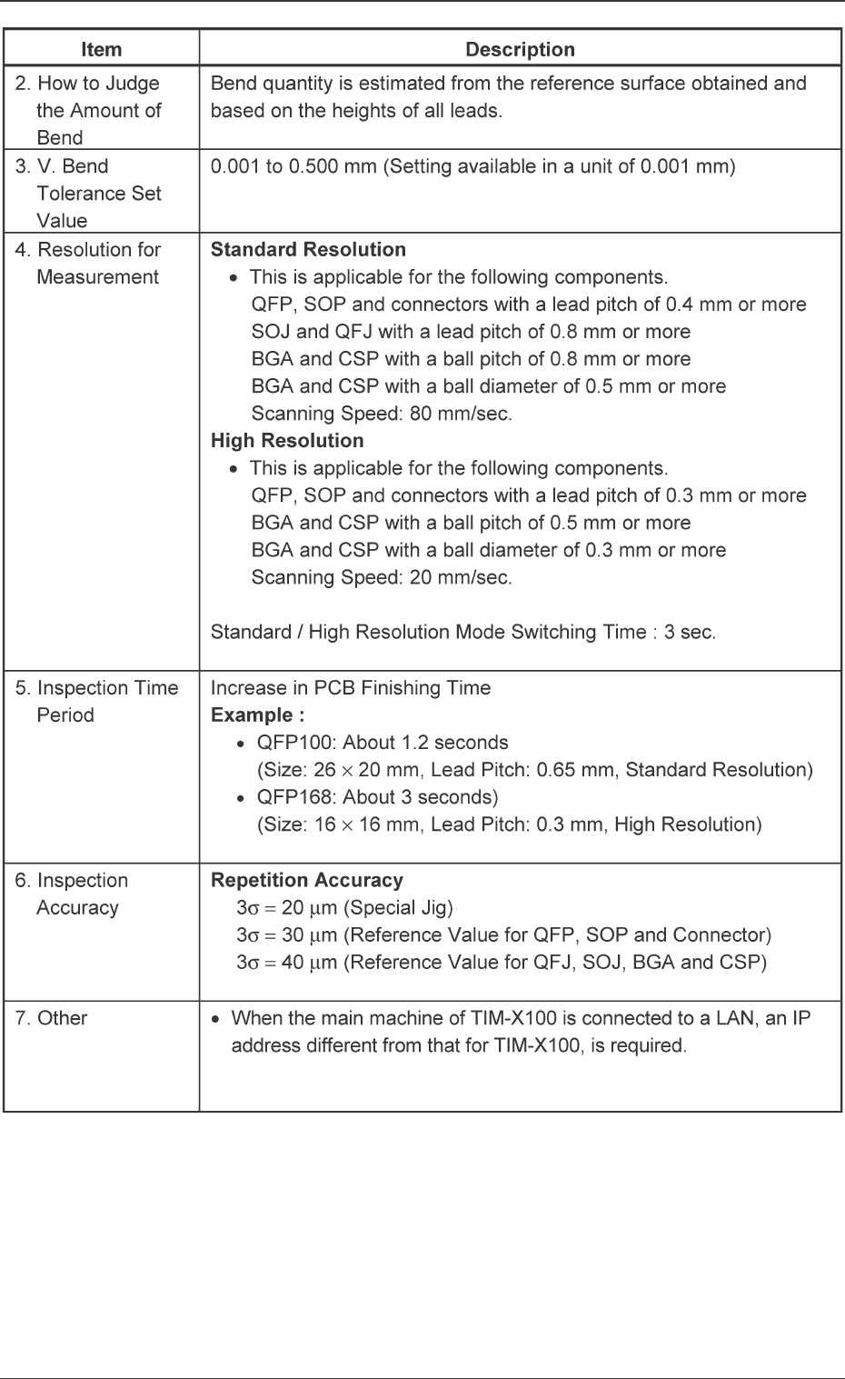
2. Specifications
16 Tg0742-PM-SO0301-001
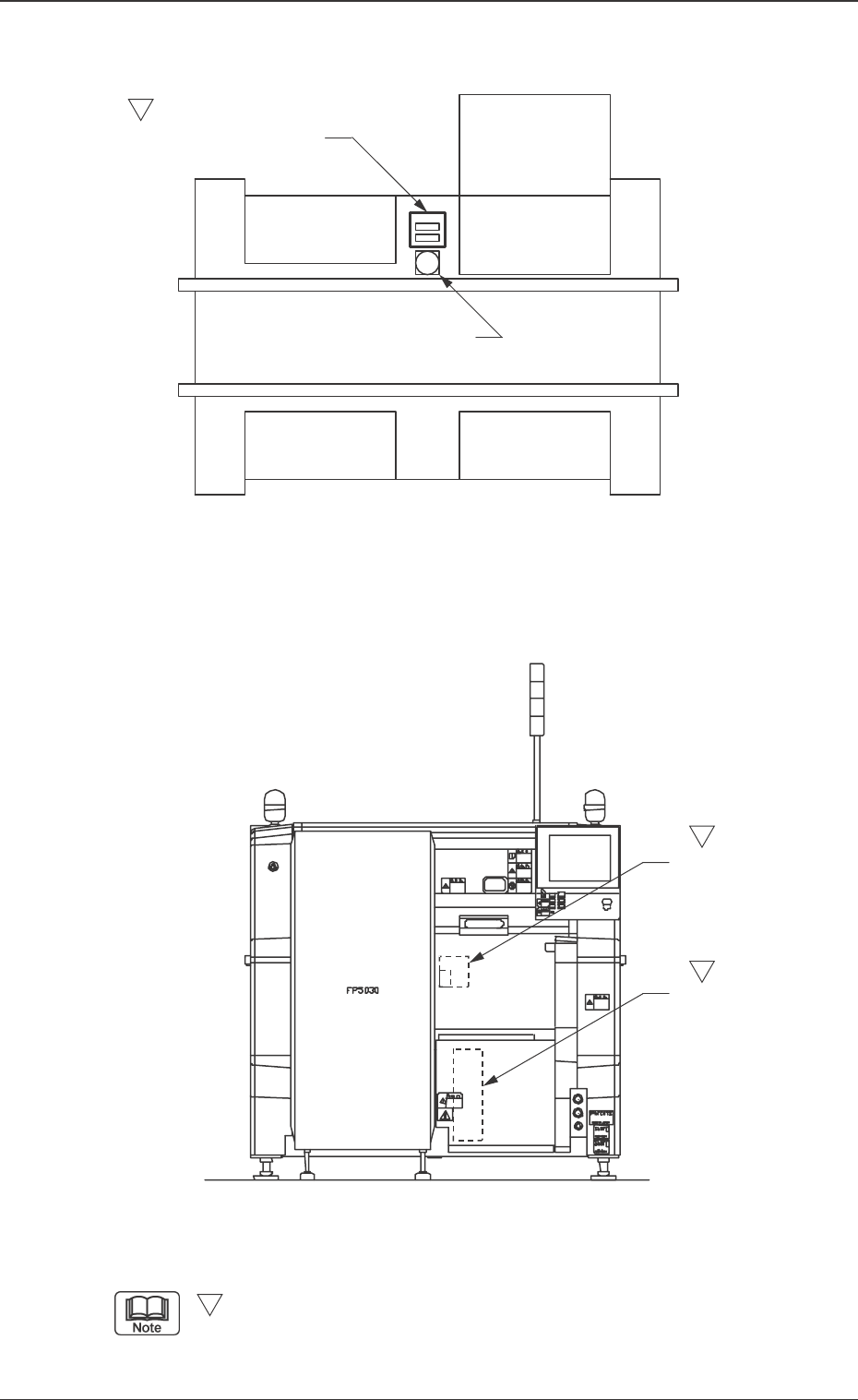
3. Rough View of Machine
Fig. 2 V. Bend Detection Unit
Fig. 1 Main Machine of TIM-X100
3. Rough View of Machine
-marked area is specially specified.
S
(Front Side of Machine)
S
S
S
V. Bend Detection
Sensor Head
V. Bend Detection Unit
Controller
Feeder Base
Feeder Base
Feeder Base
Tray Feeder
Fixed Recognition Camera
V. Bend Detection Unit
17 Tg0742-PM-SO0301-001
4.Scope of Actions
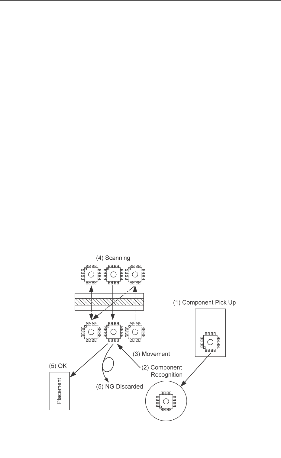
4. Scope of Actions
(1) The component is picked up (taken out) from the feeder.
(2) The component recognition operation is performed.
(3) The placement head is moved to the position where the V. bend
detection is performed.
• While the placement head is moving, the following actions are
performed.
The placement head stands by at the position where the scan-
ning is started.
X, Y and Z are corrected for the component to be picked up
based on the component recognition results.
The component stands by at the specified angle where the
scanning is started.
(4) V. bend detection is performed.
• Batch Scanning is employed for batch detection.
• Scanning is performed twice for divided detection.
(5) The following processing is performed based on the V. bend detec-
tion results.
OK: The component is placed.
NG: The component is discarded.
Ref. : The V. bend judgment criteria are set in the component
library.
Fig. 3