SOM-1655-002.pdf - 第32页
31 Tg0742-PM-SO 9. Maintenance 9.1 Periodic Maintenance 9.1.1 Precautionary Items This section describes how to perform lubrication, inspections, and cleaning work to keep the machine in good working condition. It is rec…
30 Tg0742-PM-SO
Error ID Item
6b3021 Terminal Detection Error
(without Image) [3020]
6b3031 Measuring Image Error [3030]
6b3041 Terminal (Ball, Lead) Detection
Error (Data not corresponding)
[3040]
6b3061 Installation Position Correction
Error [3060]
6b3081 Terminal Detection Error
(Missing) [3080]
6b3101 Component Inclination Error
[3100]
6b3111 Terminal (Ball, Lead) Detection
Error (Too Close to Sensor)
[3110]
6b3121 Terminal (Ball, Lead) Detection
Error (Too Far from Sensor)
[3120]
6b3131 Terminal (Ball, Lead) Detection
Error (Blurred Image) [3130]
6b3141 Terminal (Ball, Lead) Detection
Error (Blurred Image) [3140]
6b9001 Software Malfunction [9000]
0301-001
8.Troubleshooting after Error Window (Error ID)
Description
The image for measurement is not correctly scanned. Check
the data for the position of the terminal (ball, lead), pitch,
component size and component thickness.
The image for measurement is not correctly scanned.Check
the component size and pick-up position.
The component data differs greatly from the image for
measurement. Check the data for the terminal (ball, lead)
position, pitch, component size and component thickness.
When the installation position is corrected, the correction
jig is not recognized. The sensor head might be incorrectly
installed. Check the correction gauge attachment condition
and the unit installation.
Some terminals cannot be detected (missing terminal).
Check the data for lead or ball position, and number of
leads.
The component inclination degree is larger than the virtual
plane allowance.
Check the component pick-up surface and condition.
Part of the component exceeds the lower limit of the
measurement area. Check the component thickness data,
and the V. bend unit height offset.
Part of the component exceeds the upper limit of the
measurement area.
Check the component thickness data, and the V. bend unit
height offset.
The image of the lead is blurred so that the lead cannot be
correctly detected.
Lower the dark level (dlv) in the component library data.
As part of the terminal's reflection is excessive, the termi-
nal cannot be correctly detected. Lower the laser power
(lpw) or set the AGC range in the component library data
to <2>.
The V. bend detection unit is malfunctioning. If the error
still occurs after the power is turned on again, contact our
service personnel for details.
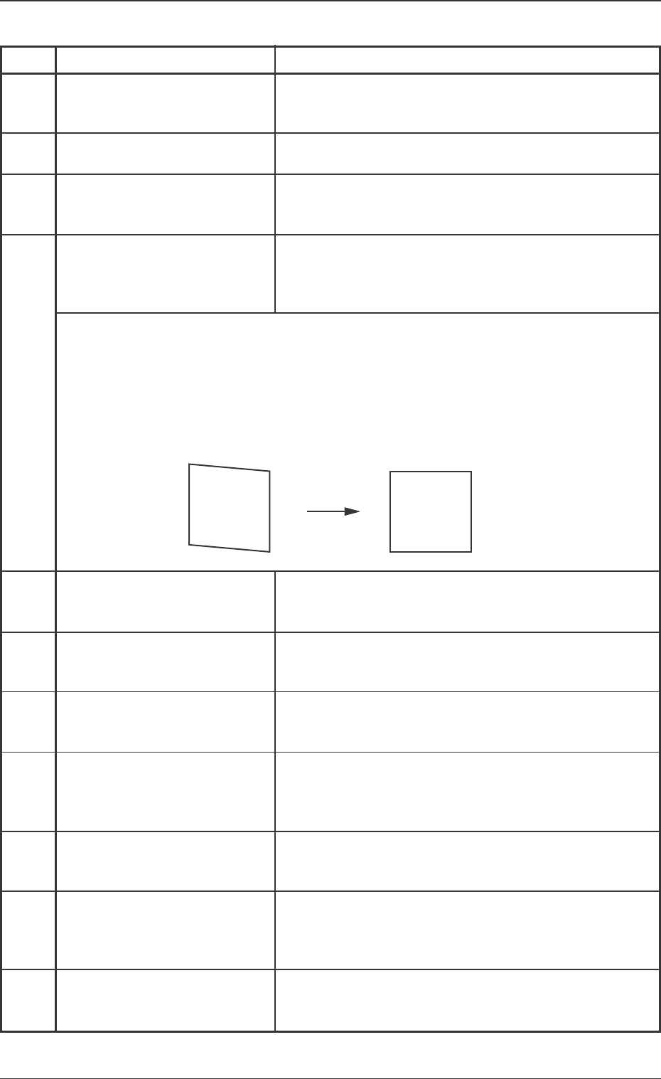
(Cause) Adjust the installation in ω3 direction so that the image becomes correctly
square.When the image of the "Sensor Head Installation Adjustment" display is
not correctly square (parallelogram), it is treated is an error, because the devia-
tion in ω3 direction is too large.
(Remedy 1) Adjust the installation in ω3 direction so that the image becomes correctly
square.
31 Tg0742-PM-SO
9. Maintenance
9.1 Periodic Maintenance
9.1.1 Precautionary Items
This section describes how to perform lubrication, inspections, and
cleaning work to keep the machine in good working condition. It is
recommended that the maintenance work be performed periodi-
cally.
• Do not air-blow.
If dirt and dust are dispersed, they adhere to various sensors,
ball screw, linear guide, etc., causing the machine break down.
• If the V. bend detection unit is operated with dirt and dust accu-
mulated, it will result in incorrect recognition.
9.1.2 Preparation for Maintenance
Preparation for Cleaning
Prepare the cleaning tools.
• Rag
Use a clean rag (cotton, etc.) which is as less waste thread as
possible.
0301-001
9. Maintenance
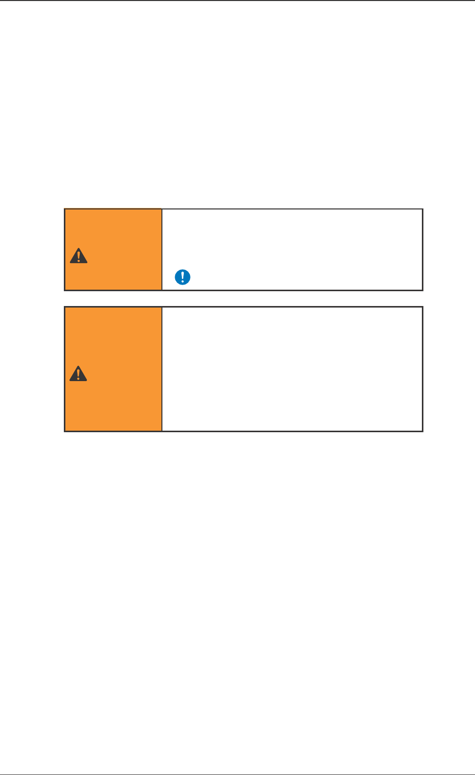
• Only qualified personnel should perform the
maintenance work carefully, following the
specified instructions.
WARNING
• Before performing maintenance work, turn off
the power and air source and lock the power
breaker using the padlock.
• Designate a person who can have charge of
the padlock key.
Refer to the Instruction Manual of the Main
Machine for details.
WARNING
32 Tg0742-PM-SO
9.1.4 Weekly Maintenance
9.1 Periodic Maintenance
0301-001
9.1.3 Daily Maintenance
Maintenance Spots
Description
Fig. No.
Required
Items
Check
V. Bend Detection Unit
13
Checking and
Cleaning
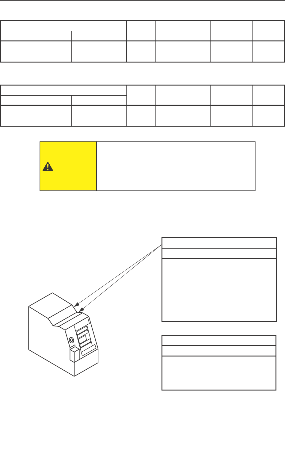
Fig. 13 V. Bend Detection Unit
Sensor Head Top
Every Day Checking and Cleaning
• Check visually that no foreign mat-
ter has accumulated when the op-
eration is started.
• If any foreign matter has accumu-
lated, remove it by hand.
Note: Do not air-blow.
Sensor Head Top
Every Week Cleaning
• Wipe off dirt and dust using a clean
rag.
Note: Do not air-blow.
Block Name Detailed Name
Sensor Head Top
Rag. etc.
Maintenance Spots
Fig. No.
Required
Items
Check
V. Bend Detection Unit
13
Cleaning
Block Name Detailed Name
Rag
The operator has to enter the machine in this work.
Before performing maintenance work, turn off the
power switch of the machine and the air source and
lock the power breaker using the padlock.
CAUTION
Sensor Head Top
Description