SOM-1655-002.pdf - 第26页
25 Tg0742-PM-SO 0301-001 7. Component Library XY posn detn Auto (Default) : The XY posn allowance is set automatically . Normally , it is set to 0.3 mm. Disable : The XY posn detn for each lead is not decided. (Unavailab…

24 Tg0742-PM-SO0301-001
7. Component Library
Laser power
Auto :
The laser power is set to "7" (Maximum).
From 1 to 7 :
The laser power can be changed between 1 and 7. When
the lead (ball) is reflected too much and there is a bright
alarm error, reduce the laser power.
Dark cut level set
Auto (Default) :
The dark cut level is set to the following values, depending
on the settings for component characteristics.
In the case of Leaded Components
Luster: 60, Half-Luster: 40, Non-Luster: 20
Solder Ball Component
Luster: 40, Half-Luster: 40, Non-Luster: 20
Manual :
The dark cut level can be set manually.
Dark cut level
This is indicated when the dark cut level is set to "Manual". It
is set when the dark cut level has to be adjusted, depending
on the lead image, resulting from checking the indicated
distance and image of the V. bend detection sensor head
after recognition test.
AGC range
Auto (Default) :
The AGC (Auto Gain Control) is set to "2" for gull wing and
J bend leaded components. It is set to "3" for straight and
solder ball components.
From 1 to 5 :
The AGC can be set in the range of 1 and 5.
When the difference between reflections of leads is
great and the V. bend detection result is not stable,
reduce the value.
25 Tg0742-PM-SO0301-001
7. Component Library
XY posn detn
Auto (Default) :
The XY posn allowance is set automatically. Normally, it is
set to 0.3 mm.
Disable :
The XY posn detn for each lead is not decided.
(Unavailable)
Enable :
The XY posn allowance is set manually.
XY posn allowance
It is displayed when the "XY posn detn" is set to "Enable".
The XY posn allowance for each lead is entered.
Lead sampling posn set
Auto (Default) :
If the lead shape is gull wing, it is set to "0.1 mm"; if J
bend, it is set at a value corresponding to a half the lead
length.
Manual :
The Lead sampling posn sis set manually.
This function is valid only when the lead shape is gull wing
or straight.
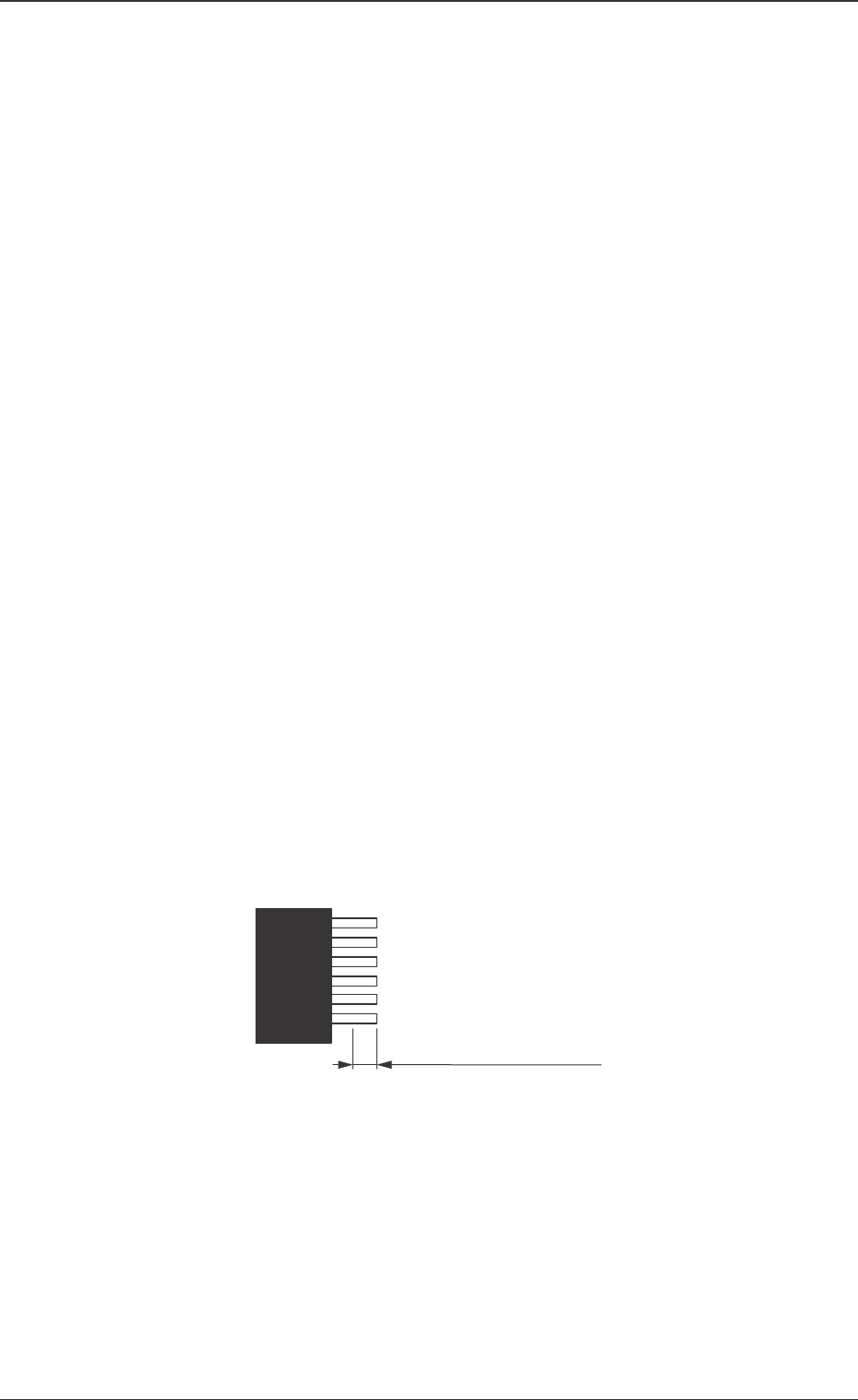
Lead sampling posn
It is displayed when the "Lead sampling posn set" is set to
"Manual". The location where the lead height is detected is
designated depending on the distance from the lead end.
Fig. 10
Designating the distance
from the edge.
26 Tg0742-PM-SO0301-001
7. Component Library
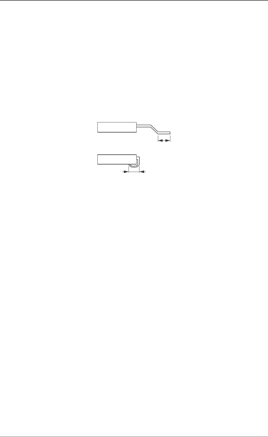
Fig. 11
Sampling scan mode
All scan :
The V. bend detection is made for all leads.
Mode 1 (Sampling) :
The V. bend detection is made periodically. The first test,
of the number of detection times set in "Sampling scan", is
made.
Sampling scan frequency 1
The frequency for the V. bend detection is set.
When the "Sampling scan mode" is set to "Mode 1 (Sam-
pling)", the first test, of the number of detection times
there, is made.
Soldered posn length set
Auto (Default) :
With gull-wing, half the total length of the lead is set.
For J bend, the total length of the lead is set.
Manual :
The "Soldered posn length" is set manually.
Soldered posn length
It is displayed when the "Soldered posn length set" is to be
set manually.
The length of the lead to be soldered is entered.