SOM-1655-002.pdf - 第48页
47 Tg0742-PM-SO 12.1 Adjustment for Sensor Head Installation 0301-001 Select Head The head to be detected is selected. Select [X1 Head] or [X2 Head]. Select Nozzle The nozzle clamp to be detected is selected. Select [Noz…
46 Tg0742-PM-SO
12.1 Adjustment for Sensor Head Installation
This window is used for the installation and adjustment of the
sensor head.
Normally, no operation is performed in this window.
12.1 Adjustment for Sensor Head Installation
0301-001
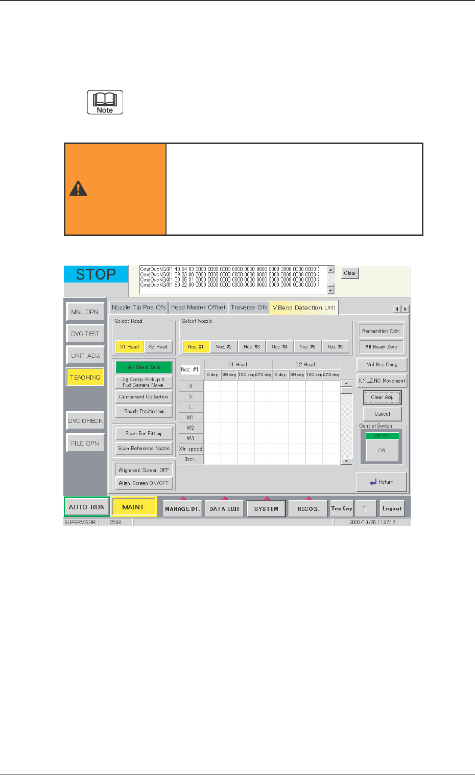
Fig. 27 "Insp Head Adj" Window
The operation of the adjustment for sensor head
installation function greatly affects the V. bend
detection accuracy. Therefore, only our service
personnel, or other persons accustomed to
teaching, should operate it.
WARNING

47 Tg0742-PM-SO
12.1 Adjustment for Sensor Head Installation
0301-001
Select Head
The head to be detected is selected.
Select [X1 Head] or [X2 Head].
Select Nozzle
The nozzle clamp to be detected is selected.
Select [Noz. #1], [Noz. #2], [Noz. #3], [Noz. #4], [Noz. #5] or
[Noz. #6].
V. Bend Detection Unit Detected Value Display
The detected values are shown in the center of the display, and
are the result of the detections of the installation correction jigs
for the head and nozzle at the angles of 0 deg, 90 deg, 180 deg
and 270 deg, respectively, using the V. bend detection unit. X, Y,
L, W1, W2, W3, Xfr speed (Transfer Speed), and Incr. (Increment
Amount) are displayed as the detection results. The sensor head
position is adjusted on the basis of these detection results.
X : Detected Value for Deviation X
Y : Detected Value for Deviation Y
L : Detected Value for Deviation L (Height)
W1 : Inclination of Sensor Head X-axis from Vertical Line
W2 : Inclination of Sensor Head Y-axis from Vertical Line
W3 : Inclination of Sensor Head Y-axis from Horizontal
Line
Xfr Speed : Transfer Speed of Jig in the Detection
Incr. : Detected Jig Size
[Recognition Dsbl.] Button
When the background is colored red, the recognition using the
camera is not available. When the detection is performed without
positioning the jig, the installation is not performed correctly.
Cancel the "Recognition Dsbl." setting.
[All Beam Zero] Button (The right of the window)
When the background is colored red, the beam cannot be zeroed,
so the detection is not available.
[Align. Screen ON/OFF] Button
Indicates that the alignment screen is displayed (or not displayed)
on the V. bend detection unit.
When the alignment screen is ON, the detection is not available
in the V. bend detection unit.

48 Tg0742-PM-SO0301-001
12.1 Adjustment for Sensor Head Installation
[All Beam Zero] Button (The left of the window)
Each of the X-, Y-, and L-axis are zeroed.
For actual proceed, press the [ON] button and then start by
pressing the [ENABLE] button on the operation panel.
[Jig Comp. Pickup & Fxd Camera Move] Button
After picking up the correction jig by the specified nozzle on the
specified head, the nozzle is moved into position for the camera
A1 and recognized by the camera.
Before this operation, the vacuum nozzle has to be
attached onto the head.
[Component Collection] Button
The correction jig picked up by the specified nozzle on the speci-
fied head is returned to the jig stocker.
• If the head and the nozzle for picking up the jig are not cor-
rectly specified, the jig cannot be returned.
• When the sensor head position is moved, the jig stocker posi-
tion is also changed and the jig cannot be correctly returned. In
this case, remove the jig manually, and return the jig to the
stocker after the jig returning operation of the machine.
[Rough Positioning] Button
The jig is moved to the center of the detection area for rough
positioning of the sensor head.
Before this operation, the vacuum nozzle has to be
attached to the head.