SOM-1655-002.pdf - 第37页
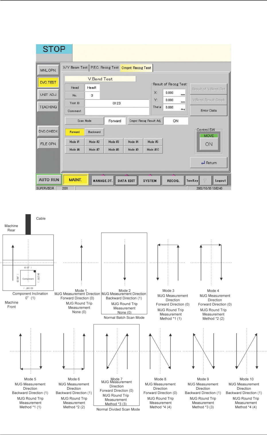
36 Tg0742-PM-SO 0301-001 [Scan Mode] Button The scanning mode for measurement is set. When this button is pressed, the following window appears. 10.2 "V . Bend T est" Window Fig. 18 Scan Movement in Each Scan M…
35 Tg0742-PM-SO
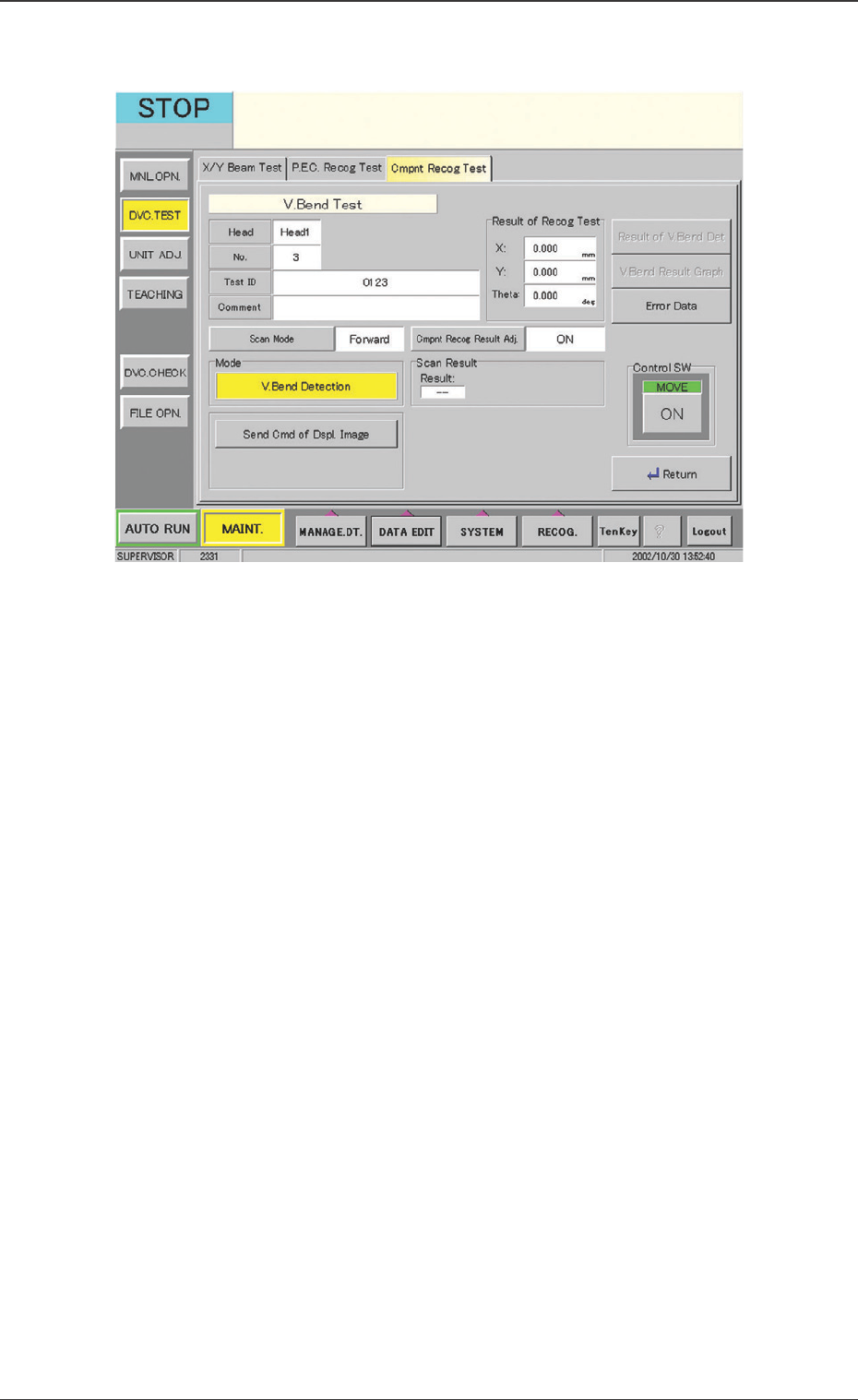
Fig. 16 "V. Bend Test" Window
10.2 "V. Bend Test" Window
••
••
• Window Composition
Head
The component pick-up head is displayed.
No.
The registration No. for the Test ID is displayed.
Test ID
The test ID is displayed.
Comment
The "Comment" for the test ID is displayed.
Result of Recog Test
The results of the component recognition test are displayed.
10.2 "V. Bend Test" Window
0301-001
36 Tg0742-PM-SO0301-001
[Scan Mode] Button
The scanning mode for measurement is set. When this button
is pressed, the following window appears.
10.2 "V. Bend Test" Window
Fig. 18 Scan Movement in Each Scan Mode
Fig. 17 "Scan Mode" Window
37 Tg0742-PM-SO
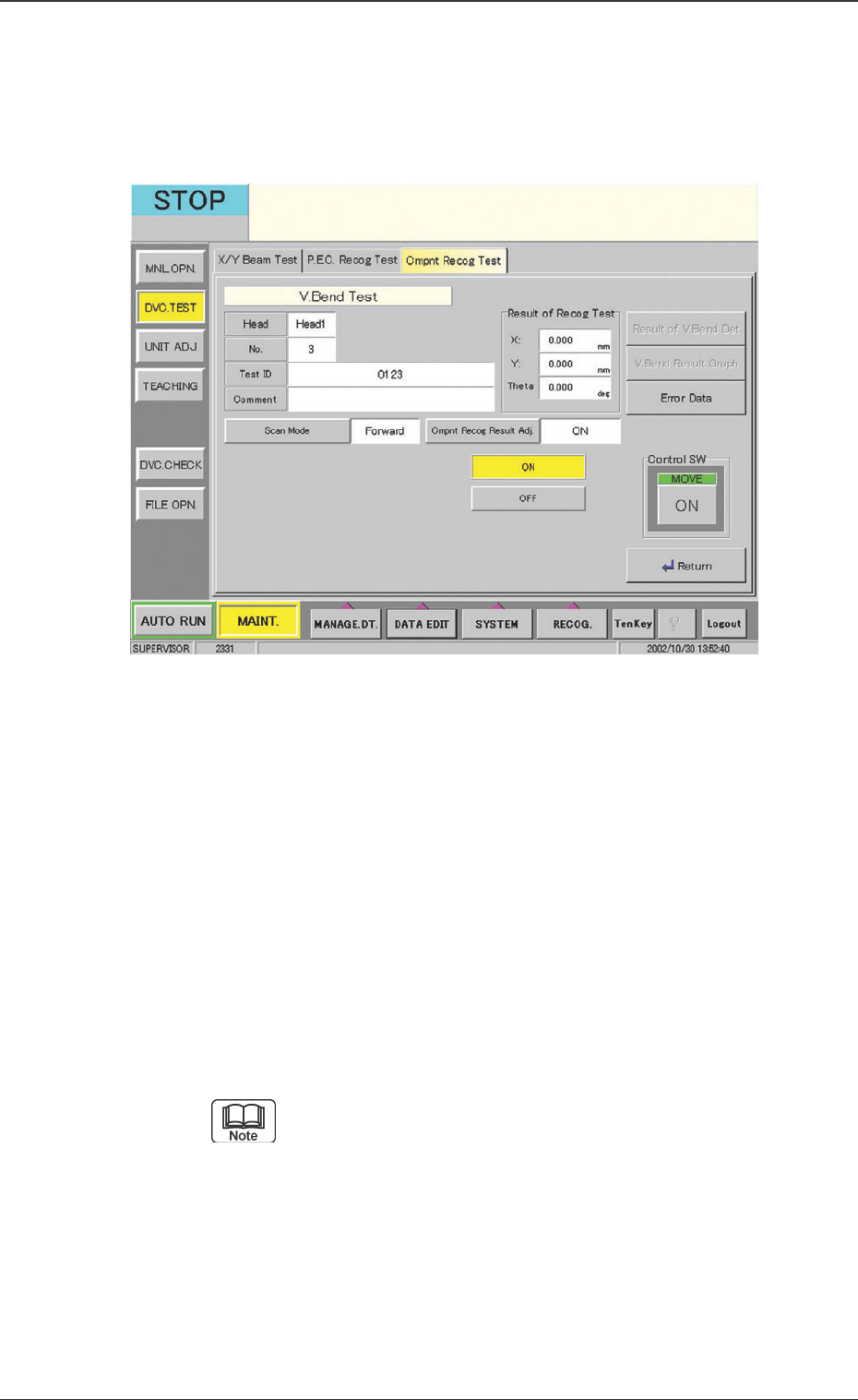
Fig. 19 "Component Recog Test" Window
[Cmpnt Recog Result Adj.] Button
Using the camera, the positional adjustment is set, based on
the component recognition results. When this button is
pressed, the following window appears.
Operation Procedure
(1) After pressing the [V. Bend Detection] button, press the
"Control SW" [ON] button.
(2) When the [MOVE] switch is pressed, the V. bend is
detected.
[Send Cmd of Dspl. Image] Button
When the [Send Cmd of Dspl. Image] button is pressed, the
command sends the detection’s resultant image to the monitor
in the V. bend detection unit.
Pressing [Ctrl] key twice switches the display to the
monitor display in the V. bend detection unit.
0301-001
10.2 "V. Bend Test" Window