SOM-1655-002.pdf - 第76页
75 Tg0742-PM-SO 14. Circuit Diagrams 0307-002-(M750WD--A3102) I/O Board IO01 (1/2) Note (a) The drain line is connected to terminal No.7 on the connector . (b) The diagram within broken lines shows one within relay PCB (…
74 Tg0742-PM-SO
14. Circuit Diagrams
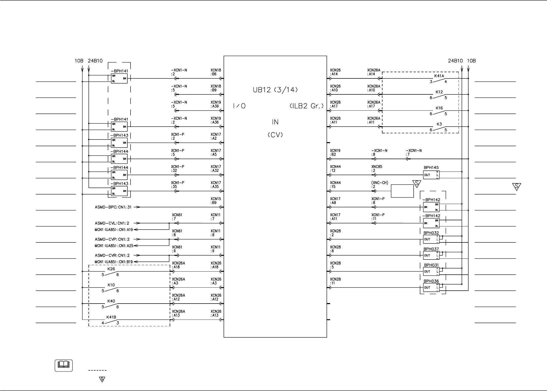
0307-002-(M750WD--A3101)
I/O Board ILB2 (1/2)
PCB Detection L1
Reserved Input
Reserved Input
PCB Detection R2
PCB Detection P1
PCB Detection P2
PCB Detection P3
PCB Detection P4
BPC-Axis Alarm
CVP-Axis Alarm
CVR-Axis Alarm
Beam Load Power
Shut-Off Detection
Air Pressure Drop
Detection
Emergency Stop
Detection
Safety Door
Detection B
CVL-Axis Alarm
MAIN BOARD
Note (b)
Note (b)
Note (a)
PC Selector
Safety Door
Detection A
Integrated CB Alarm
Load Power Supply
Shut-Off Detection
Control Power
Shut-Off Detection
BPC Base Lower
Limit Detection
PCB Positioning
Reference Direction Check
PC Selector
Condition Detection
PCB Detection L2
PCB Detection R1
Y1-Axis Limit (-)
Y2-Axis Limit (-)
Y1-Axis Limit (+)
Y2-Axis Limit (+)
Note
(a) It will be opened in the case of front reference.
(b) The diagram within broken lines shows one within relay PCB (UA96).
(c) The -marked area is specially specified.
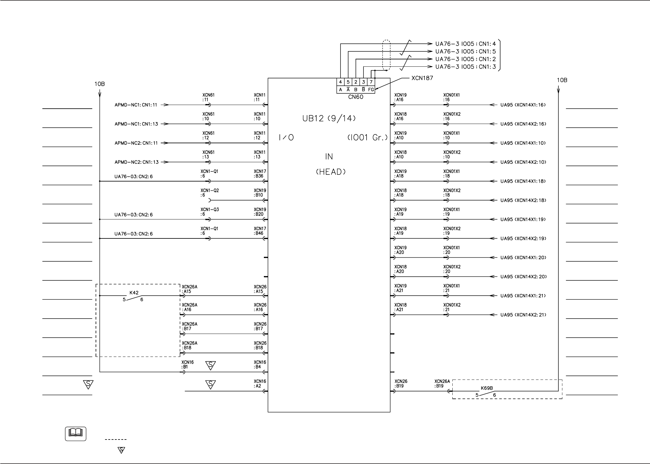
75 Tg0742-PM-SO
14. Circuit Diagrams
0307-002-(M750WD--A3102)
I/O Board IO01 (1/2)
Note
(a) The drain line is connected to terminal No.7 on the connector.
(b) The diagram within broken lines shows one within relay PCB (UA96).
(c) The -marked area is specially specified.
NC1-Axis Error (E+)
NC2-Axis Error (E+)
Reserved Input
V. Bend
Option Detection
V. Bend
Reserved Input
MAIN BOARD
Note (b)
NC1-Axis Overheat
(H+)
NC2-Axis Overheat
(H+)
Feeder Base #1
Connection Check
Feeder Base #4
Connection Check
Feeder Base #3
Connection Check
Feeder Base #2
Connection Check
Safety Door
Electromagnetic
Lock Check
Bar Code Reader
Option Detection 1
(BCR1)
Bar Code Reader
Option Detection 2
(BCR2)
Note (b)
Note (a)
Reserved Input
Reserved Input
Head #1 Vacuum
Sensor Input2
Head #1 Bad
Mark Sensor
Power Control Relay
Check during Setup
Operation
Head #2 Vacuum
Sensor Input2
Head #2 Bad
Mark Sensor
Head 1 Bad Mark
Option Detection
Head 2 Bad Mark
Option Detection
Head #2 Vacuum
Sensor Input1
Head #1 Vacuum
Sensor Input1
Reserved Input
Reserved Input
Feeder Base #1:
Feeder Base #3:
Feeder Base #4:
Shielded
To Feeder Base #4
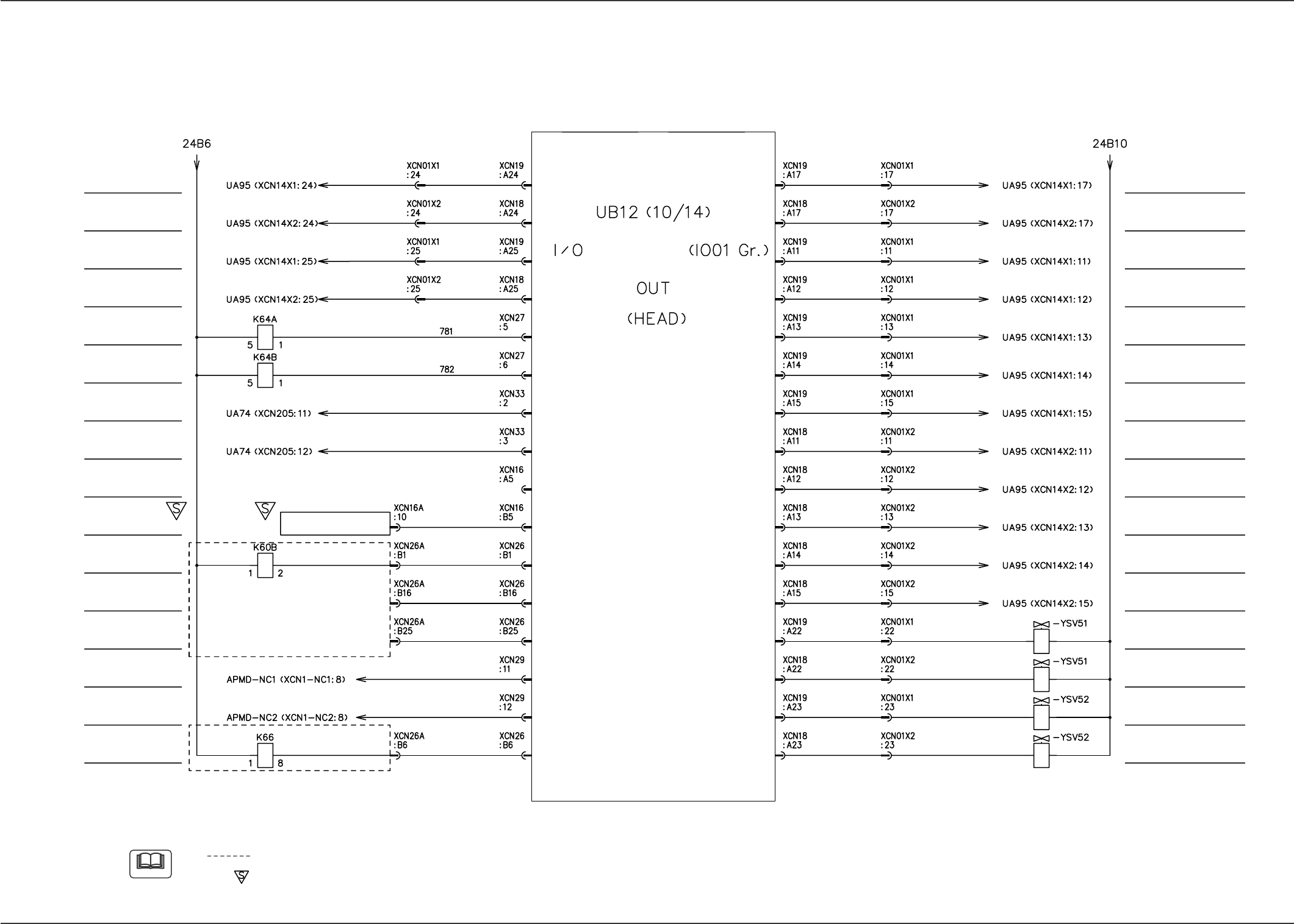
76 Tg0742-PM-SO
14. Circuit Diagrams
0307-002-(M750WD--A3103)
I/O Board IO01 (2/2)
Note
(a) The diagram within broken lines shows one within relay PCB (UA96).
(b) The -marked area is specially specified.
Reserved Output
Current Boost (I-)
’NC(1)
Vertica Bend
Power OFF
MAIN BOARD
Note (a)
Note (a)
Electro magnetic
Valve 1 : Head 1
Reserved Output
Electro magnetic
Valve 1 : Head 2
Reserved Output
Electro magnetic
Valve 2 : Head 1
Reserved Output
Electro magnetic
Valve 2 : Head 2
Reserved Output
L1-Axis Brake
Forced Release
L2-Axis Brake
Forced Release
Image Capture
Trigger 1
Image Capture
Trigger 2
Reserved Output
V. Bend Detection
(Option)
Measurment
Start Signal
(V. Bend Detection)
Beam Load Power
Supply
Reserved Output
Current Boost (I-)
’NC(2)
V. Bend Detection Unit
Reserved Output
Reserved Output
Head #1 Bad Mark Sensor
(REMOTE)
Head #1 Vacuum Sensor
(AS)
Head #1 Vacuum Sensor
(Sel2)
Head #1 Vacuum Sensor
(Sel1)
Head #1 Vacuum Sensor
(Sel0)
Head #2 Bad Mark Sensor
(REMOTE)
Head #2 Vacuum Sensor
(AS)
Head #2 Vacuum Sensor
(Sel2)
Head #2 Vacuum Sensor
(Sel1)
Head #2 Vacuum Sensor
(Sel0)
Head #2 Vacuum
Head #1 Vacuum
Head #1 Vacuum Breaker
Head #2 Vacuum Breaker