SOM-1655-002.pdf - 第75页
74 Tg0742-PM-SO 14. Circuit Diagrams 0307-002-(M750WD--A3101) I/O Board ILB2 (1/2) PCB Detection L1 Reserved Input Reserved Input PCB Detection R2 PCB Detection P1 PCB Detection P2 PCB Detection P3 PCB Detection P4 BPC-A…
73 Tg0742-PM-SO
14. Circuit Diagrams
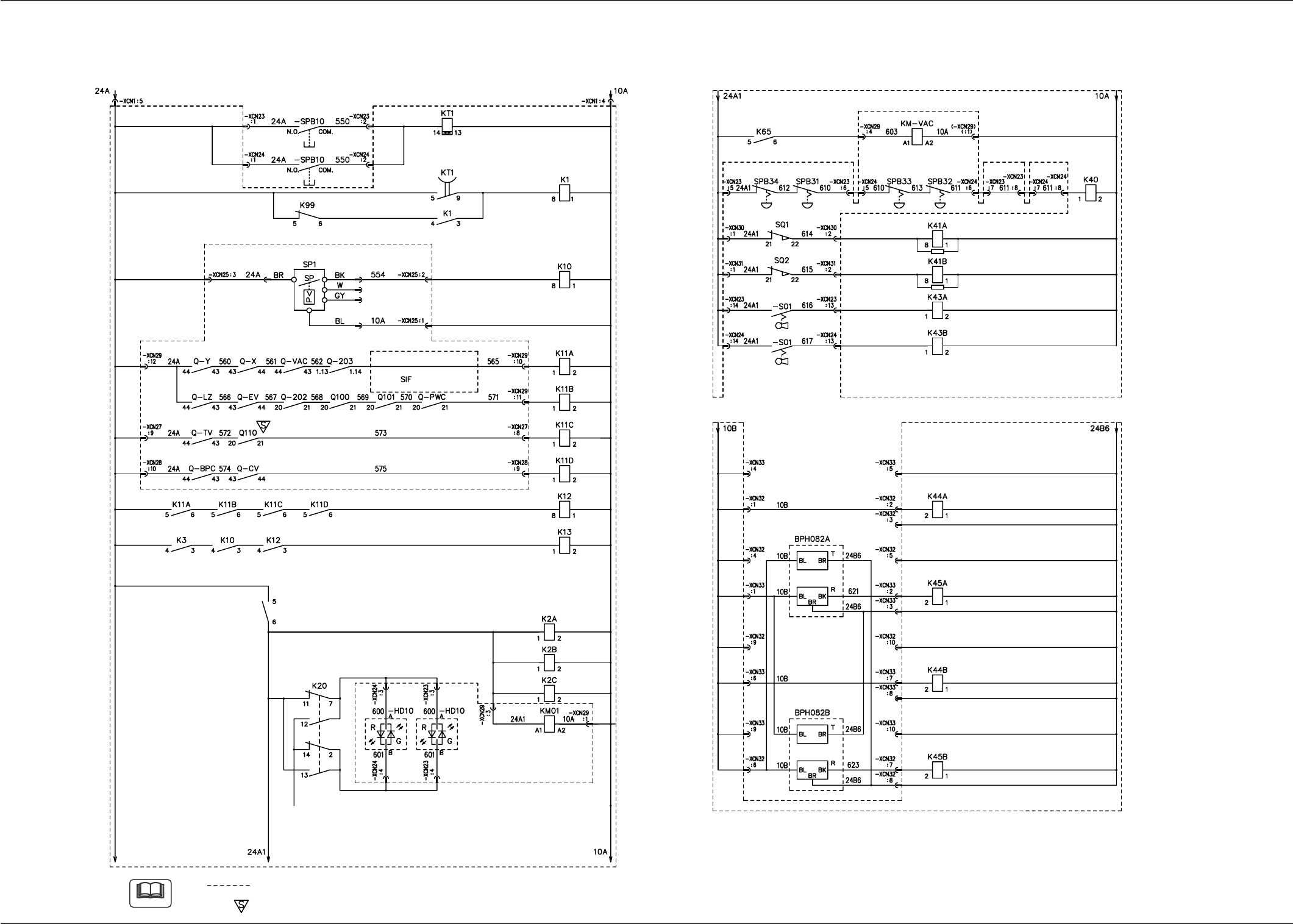
Power Circuit Diagram (4)
0307-002-(M750WB--A3103)
Vacuum Pump Mode
Emergency Stop Detection
Closed Safety Door
Detection A
SETUP (A)
Closed Safety Door
Detection B
SETUP (B)
Maintenance Opening
Detection A (Upper Side)
Maintenance Opening
Detection A (Lower Side)
Maintenance Opening
Detection B (Upper Side)
Maintenance Opening
Detection B (Lower Side)
OPERATION/SETUP
(Side A)
OPERATION/SETUP
(Side B)
(Middle Stage)
(Middle Stage)
Front Left Rear Left Front Right Rear Right
Power ON Detection
Air Pressure Drop
Detection
Power Supply
for Controls
CB Alarm 1
CB Alarm 2
CB Alarm 3
CB Alarm 4
Integrated CB Alarm
Error Detection
DC Power Supply
Remote 1 ON
DC Power Supply
Remote 2 ON
DC Power Supply
Remote 3 ON
100V AC
Power Supply
(Side A) (Side B)
Power ON Indication
K1 (For Power Loads) Power Supply for Controls
CB Alarm 1 CB Alarm 2 CB Alarm 3 CB Alarm 4
Servo C
Control Power
Shut-Off
Detection
Air Pressure
Drop Detection
Integrated
CB Alarm
Transformer 2
Option
Transformer 1
(Option)
Power Outlet
for Servicing
Power ON (A)
Power ON (B)
Power OFF Power Supply for Controls
Power Supply Detection
Pressure Switch
Note (a)
Note (a)
Note (a)
Note
(a) The diagram within broken lines shows one within relay PCB (UA96).
(b) The -marked area is specially specified.
74 Tg0742-PM-SO
14. Circuit Diagrams
0307-002-(M750WD--A3101)
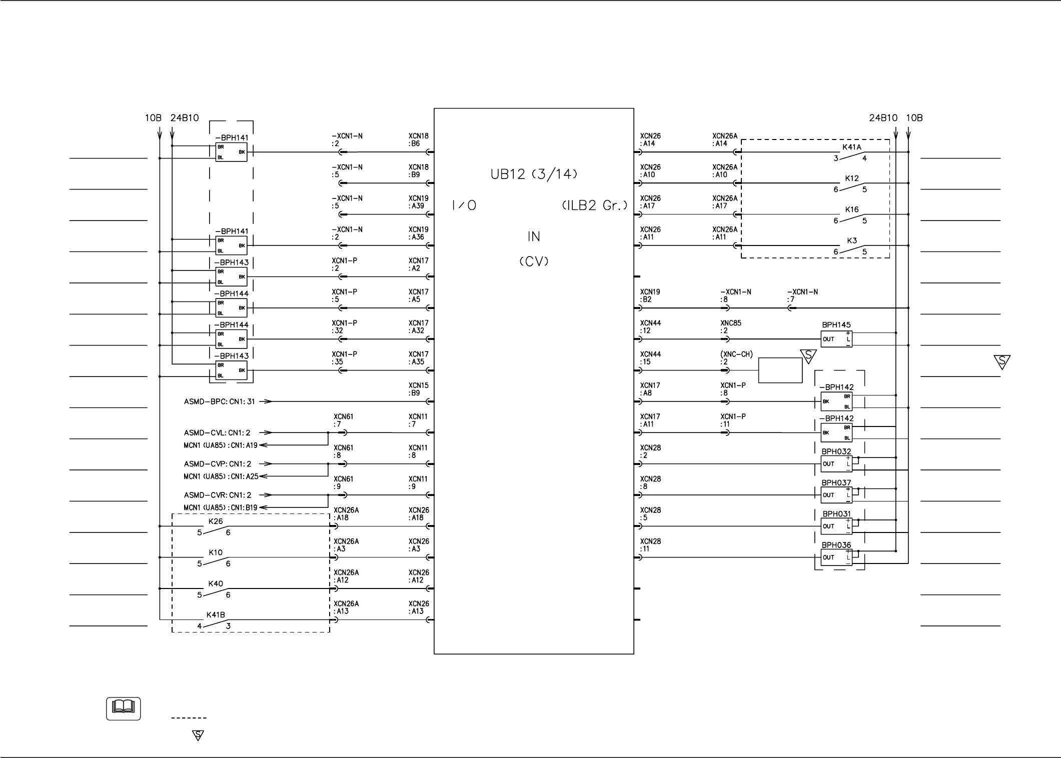
I/O Board ILB2 (1/2)
PCB Detection L1
Reserved Input
Reserved Input
PCB Detection R2
PCB Detection P1
PCB Detection P2
PCB Detection P3
PCB Detection P4
BPC-Axis Alarm
CVP-Axis Alarm
CVR-Axis Alarm
Beam Load Power
Shut-Off Detection
Air Pressure Drop
Detection
Emergency Stop
Detection
Safety Door
Detection B
CVL-Axis Alarm
MAIN BOARD
Note (b)
Note (b)
Note (a)
PC Selector
Safety Door
Detection A
Integrated CB Alarm
Load Power Supply
Shut-Off Detection
Control Power
Shut-Off Detection
BPC Base Lower
Limit Detection
PCB Positioning
Reference Direction Check
PC Selector
Condition Detection
PCB Detection L2
PCB Detection R1
Y1-Axis Limit (-)
Y2-Axis Limit (-)
Y1-Axis Limit (+)
Y2-Axis Limit (+)
Note
(a) It will be opened in the case of front reference.
(b) The diagram within broken lines shows one within relay PCB (UA96).
(c) The -marked area is specially specified.
75 Tg0742-PM-SO
14. Circuit Diagrams
0307-002-(M750WD--A3102)
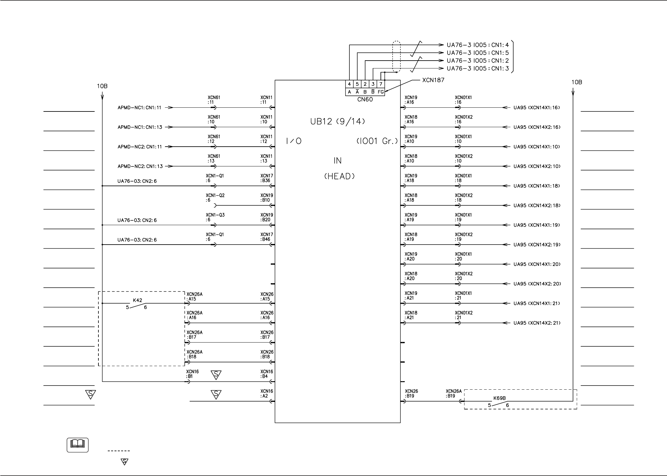
I/O Board IO01 (1/2)
Note
(a) The drain line is connected to terminal No.7 on the connector.
(b) The diagram within broken lines shows one within relay PCB (UA96).
(c) The -marked area is specially specified.
NC1-Axis Error (E+)
NC2-Axis Error (E+)
Reserved Input
V. Bend
Option Detection
V. Bend
Reserved Input
MAIN BOARD
Note (b)
NC1-Axis Overheat
(H+)
NC2-Axis Overheat
(H+)
Feeder Base #1
Connection Check
Feeder Base #4
Connection Check
Feeder Base #3
Connection Check
Feeder Base #2
Connection Check
Safety Door
Electromagnetic
Lock Check
Bar Code Reader
Option Detection 1
(BCR1)
Bar Code Reader
Option Detection 2
(BCR2)
Note (b)
Note (a)
Reserved Input
Reserved Input
Head #1 Vacuum
Sensor Input2
Head #1 Bad
Mark Sensor
Power Control Relay
Check during Setup
Operation
Head #2 Vacuum
Sensor Input2
Head #2 Bad
Mark Sensor
Head 1 Bad Mark
Option Detection
Head 2 Bad Mark
Option Detection
Head #2 Vacuum
Sensor Input1
Head #1 Vacuum
Sensor Input1
Reserved Input
Reserved Input
Feeder Base #1:
Feeder Base #3:
Feeder Base #4:
Shielded
To Feeder Base #4