SOM-1655-002.pdf - 第53页
52 Tg0742-PM-SO 0301-001 12.1 Adjustment for Sensor Head Installation Fig. 30 "Mnl Noz Chng" Window [Mnl Noz Chng] Button This is used to set or reset the vacuum nozzle onto the specified nozzle clamp when the …

51 Tg0742-PM-SO
Operation Procedure
(1) Select the head and nozzle to be detected. Attach the
vacuum nozzle on the selected nozzle clamp.
(2) After the jig is picked up by pressing the [Jig Comp. Pickup &
Fxd Camera Move], press the [Scan Reference Nozzle]
button to start scanning.
(3) For "Scan Times", the number of detection operations is set.
Normally, set it to 6.
(4) For "Direction", the direction of the jig used for detection is
set.
This should be made at angles of both 0 deg and 90 deg.
(5) The values are compared with the installation target values,
and OK or NG is indicated for the installation condition.
Adjust the sensor head so that the indications of W1 and W3 are
both "OK".
0301-001
12.1 Adjustment for Sensor Head Installation
52 Tg0742-PM-SO0301-001
12.1 Adjustment for Sensor Head Installation
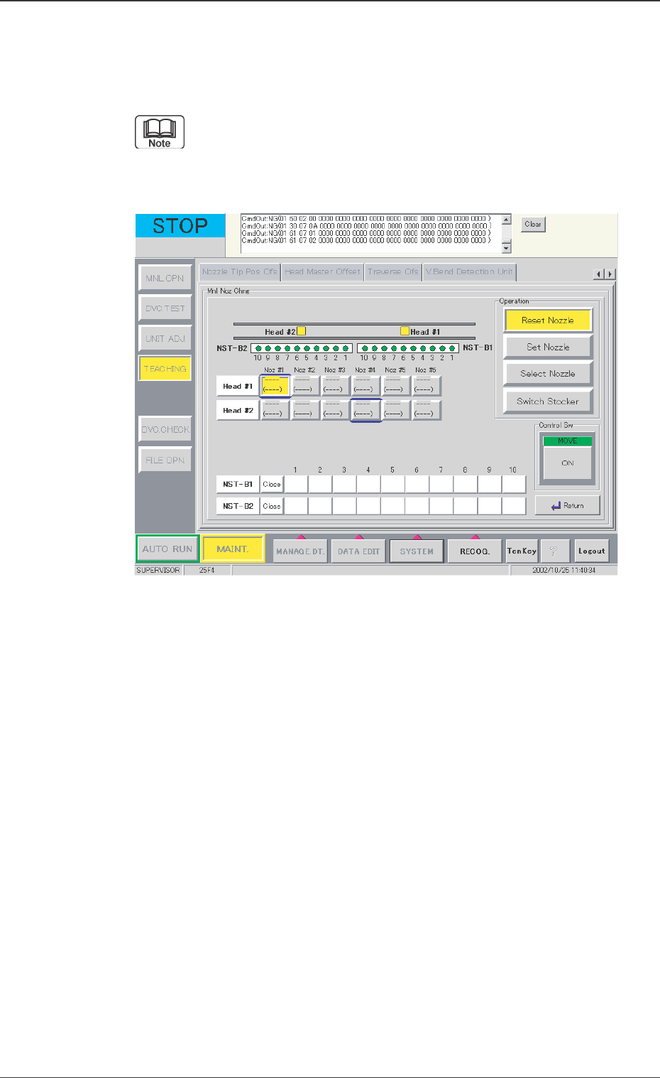
Fig. 30 "Mnl Noz Chng" Window
[Mnl Noz Chng] Button
This is used to set or reset the vacuum nozzle onto the specified
nozzle clamp when the individual head and nozzle are selected.
When this button is pressed, the following window appears.
Refer to "4.4 "Nozzle Change" Tab" in "Section 6 " (the
instruction manual (Vol. 2) of the main machine) for the
detailed information on how to operation.
53 Tg0742-PM-SO
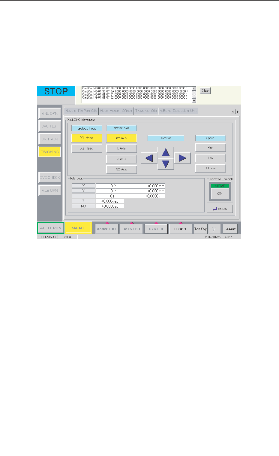
[X, Y, L, Z NC Movement] Button
This button is used when the X, Y, L, Z, or NC-axis is temporarily
moved or during rough positioning and when the position is
checked with these axes' fine movement. Before beginning such
operation, select the axis to be moved, direction, and speed.
When this button is pressed, the following window appears.
0301-001
12.1 Adjustment for Sensor Head Installation
Fig. 31 "X, Y, L, Z, NC Movement" Window