SOM-1655-002.pdf - 第60页
59 Tg0742-PM-SO 12.3 Offset T eaching The offset teaching is required when the installation condition of V . bend detection unit is changed or the placement head replaced. V . Bend Detection Unit Adjusted V alue Indicati…

58 Tg0742-PM-SO
Adjustment in
ωω
ωω
ω1 Direction
Repeatedly adjust the inclination in ω1 direction until ω1 set
condition becomes OK, using the [Scan Reference Nozzle]
function.
Adjustment in
ωω
ωω
ω3 Direction
Repeatedly adjust the inclination in ω3 direction until the ω3 set
condition becomes OK, using the [Scan Reference Nozzle]
function.
There is no problem when the ω2 set is NG (no good).
0301-001
12.2 Sensor Head Set and Adjustment Procedure
59 Tg0742-PM-SO
12.3 Offset Teaching
The offset teaching is required when the installation condition of V.
bend detection unit is changed or the placement head replaced.
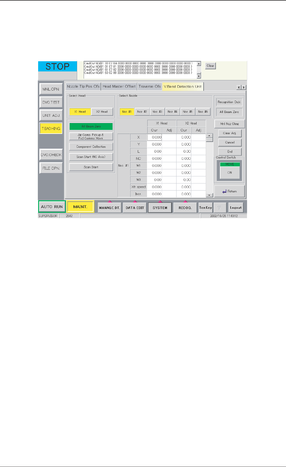
V. Bend Detection Unit Adjusted Value Indication
The current values and adjusted values for offset of each head
and nozzle are shown in the center of the window of the V. bend
detection unit.
Select Head
Select the head to be detected.
Select [X1 Head] or [X2 Head].
Select Nozzle
The nozzle clamp to be detected is selected.
Select [Noz. #1], [Noz. #2], [Noz. #3], [Noz. #4], [Noz. #5] or [Noz.
#6].
[Recognition Dsbl.] Button
When the background is colored red, the recognition using the
camera is not available. When the detection is pertormed without
positioning the jig, the installation is not performed correctly.
Cancel the "Recognition Dsbl." setting.
12.3 Offset Teaching
0301-001
Fig. 34 "Offset Teaching" Window
60 Tg0742-PM-SO
[All Beam Zero] Button (The right of the sheet)
When the background is colored red, the beam cannot be zeroed,
so that detection is not available.
[All Beam Zero] Button (The left of the sheet)
Each of the X-, Y-, and L-axis, is zeroed.
For actual procedure, press the [ON] button and then start by
pressing the [ENABLE] button on the operation panel.
[Jig Comp. Pickup & Fxd Camera Move] Button
After picking up the correction jig by the specified nozzle on the
specified head, the nozzle is moved into position for the fixed
camera A1 and recognized by the camera.
Before this operation, the vacuum nozzle has to be
attached on the head.
[Component Collection] Button
The correction jig picked up by the specified nozzle on the speci-
fied head is returned to the jig stocker.
• If the head and the nozzle for picking up the jig are not correctly
specified, the jig cannot be returned.
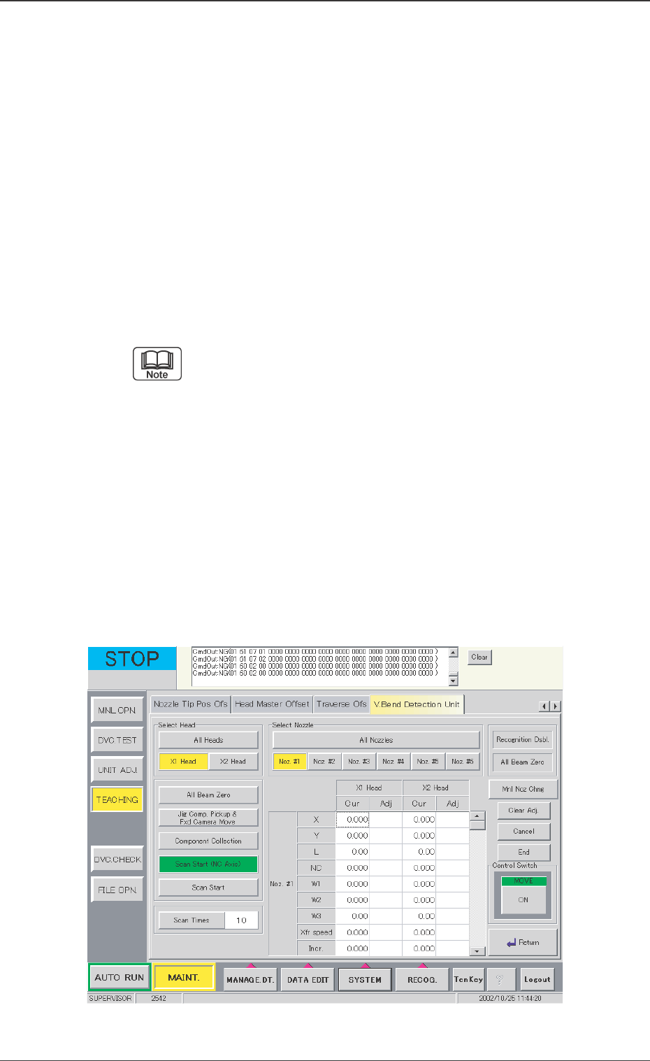
[Scan Start (NC Axis)] Button
The detecting is done by means of scanning the correction jig and
the offset values for the NC-, X-, Y- and L-axis are calculated.
12.3 Offset Teaching
0301-001
Fig. 35 "Offset Teaching" Window (Scan Start (NC-Axis))