SOM-1655-002.pdf - 第79页
78 Tg0742-PM-SO 14. Circuit Diagrams 0307-001-(M750WH--A3101) Y1- and Y2-Axis Motor Circuit Diagram Note (a) The diagram within broken lines shows one within I/O main board PCB (UB12). (b) The -marked area is specially s…
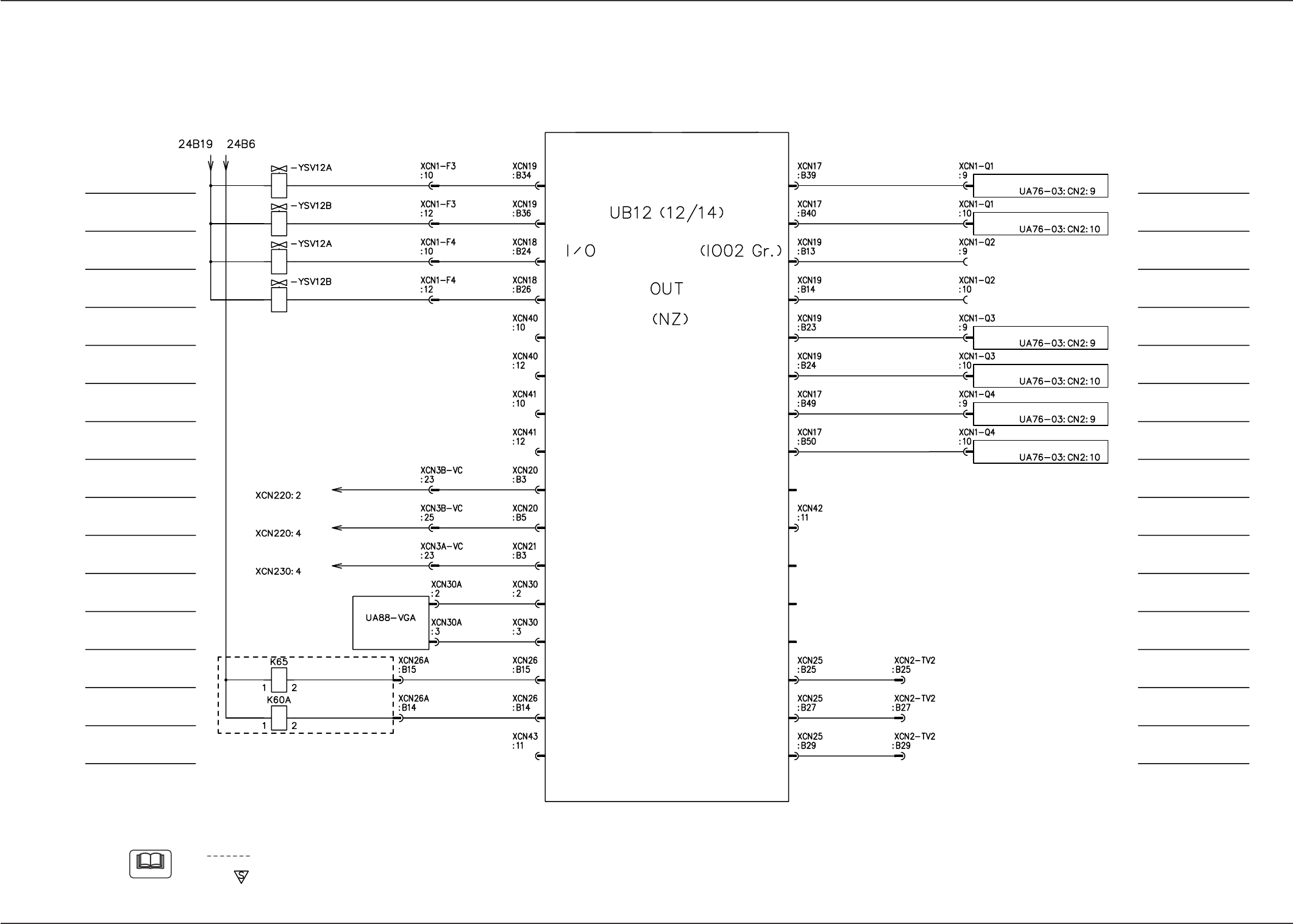
77 Tg0742-PM-SO
14. Circuit Diagrams
0307-002-(M750WD---3112)
I/O Board IO02 (2/2)
Note
(a) The diagram within broken lines shows one within relay PCB (UA96).
(b) The -marked area is specially specified.
Nozzle Stocker B1
Opening
Nozzle Stocker B2
Opening
Nozzle Stocker B1
Closing
Nozzle Stocker B2
Closing
(Nozzle Stocker A1
Opening) <Option>
Reserved Output
LCD Available Side
Selection (Front)
Back Light Control
(Front)
Front and Rear Operation
Selection Output
Front and Rear Operation
Selection Reset Output
Vaccum Pump Motor
Load Power Supply
(Nozzle Stocker A1
Closing) <Option>
Reserved Output
(Nozzle Stocker A2
Opening) <Option>
Reserved Output
(Nozzle Stocker A2
Closing) <Option>
Reserved Output
Back Light Control
(Rear)
(Recycle Conveyor B
Motor Driving) <Option>
Reserved Output
LCD Panel (Front) :
LCD Panel (Front) :
LCD Panel (Rear) :
VGA Distribution
MAIN BOARD
Note (a)
Feeder Base #1 :
Feeder Base #1 :
Feeder Base #3 :
Feeder Base #3 :
Feeder Base #4 :
Feeder Base #4 :
Feeder Base #1
Pullout Prevention Bar
Electromagnetic Lock
Feeder Base #3
Pullout Prevention Bar
Electromagnetic Lock
Feeder Base #4
Pullout Prevention Bar
Electromagnetic Lock
Feeder Base #1
Reserved Output 2
Feeder Base #3
Reserved Output 2
Feeder Base #4
Reserved Output 2
Reserved Output
Reserved Output
Traverse 2 Pallet Chuck
Claw Opening
(Option)
(Recycle Conveyor A
Motor Driving) <Option>
Reserved Output
(Traverse 2 Transfer
Rail : Up)
<Option> Reserved Output
(Traverse 2 Transfer
Rail : Down)
<Option> Reserved Output
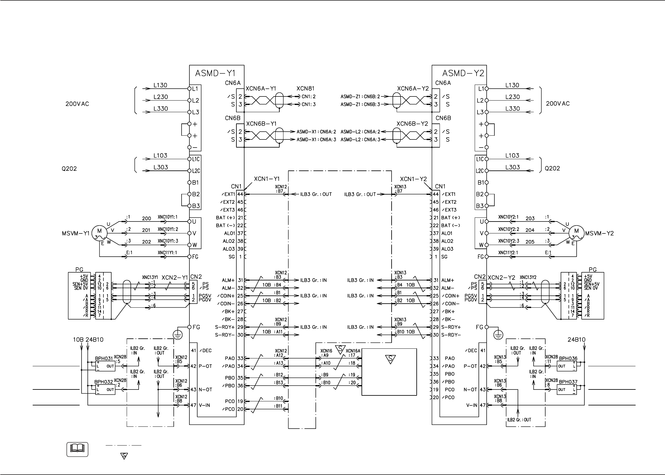
78 Tg0742-PM-SO
14. Circuit Diagrams
0307-001-(M750WH--A3101)
Y1- and Y2-Axis Motor Circuit Diagram
Note
(a) The diagram within broken lines shows one within I/O main board PCB (UB12).
(b) The -marked area is specially specified.
Y1-Axis External
Input Power Supply
Y1-Axis Limit (+)
Note (a)
Y1-Axis Limit (-)
Note (a)
Y2-Axis XCN13: To B6
S/P Converter
Control Circuit Power Supply
Main Circuit Power Supply
Y1 Axis Y2 Axis
To X1 Axis To X2 Axis
From Z1 Axis
From EB005
V. Bend Detection
Unit
From (Y1-Axis XCN12: B6)
Shielded Wires
Y2-Axis External
Input Power Supply
Y2-Axis Limit (+)
Y2-Axis Limit (-)
Control Circuit Power Supply
Main Circuit Power Supply
Note (a)
S/P Converter
Shielded Wires
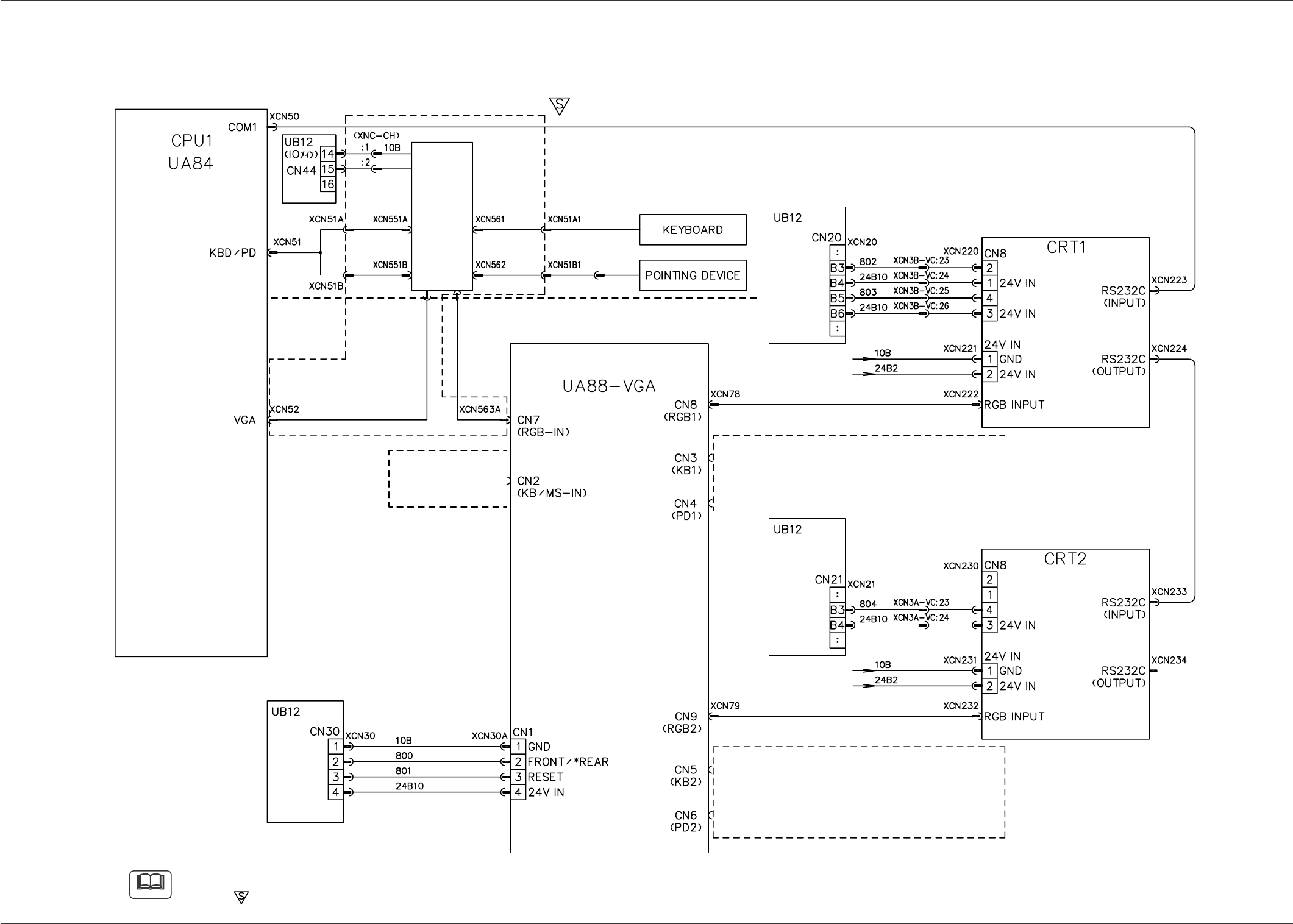
79 Tg0742-PM-SO
14. Circuit Diagrams
0307-001-(M750WC--A3101)
KB/PD/VGA Connection Diagram
Note
(a) When the optional keyboard on the side A and the pointing device are connected, PCB UA88 should be used.
(b) The -marked area is specially specified.
Note (a)
PC Selector
Keyboard and Pointing Device on Side B
VGA Distributor
LCD with Touch Screen on Side B
Touch Screen Invalid/*Vaild
Back Light OFF/*ON
Keyboard and Pointing Device on Side B
LCD with Touch Screen on Side A
Back Light OFF/*ON
Keyboard and Pointing Device on Side A
(Eqipped with the option)
(IOMB)
(IOMB)
(IOMB)
(in the standard specifications)
(Eqipped with the option)
(option)