SOM-1655-002.pdf - 第51页
50 Tg0742-PM-SO [Scan Reference Nozzle] Button After "Scan For Fitting" operation, the reference nozzle is de- cided. Then the reference nozzle is used to detect. As the sensor head installation condition is fo…
49 Tg0742-PM-SO
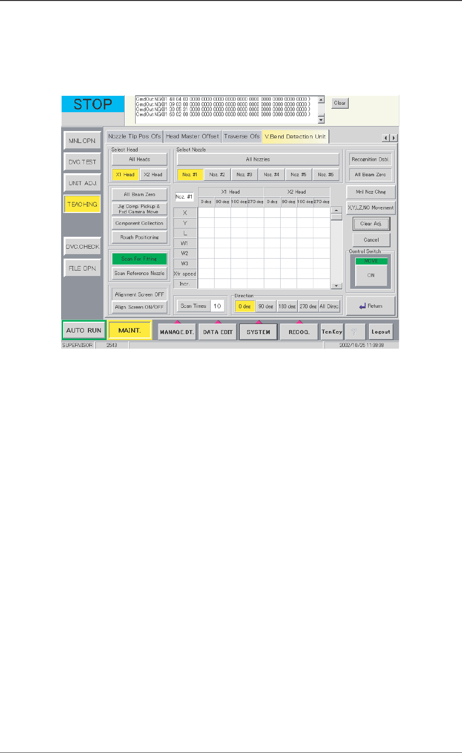
[Scan For Fitting] Button
When this button is pressed, the following window appears.
0301-001
12.1 Adjustment for Sensor Head Installation
Fig. 28 "Scan For Fitting" Window
Operation Procedure
(1) Select the head and nozzle to be detected. When the indi-
vidual head and nozzle are selected, this selected vacuum
nozzle operates as the nozzle of arrangement No. 1 (down-
ward).
When [All Heads] and [All Nozzles] are selected, before this
operation, reset the nozzle which has been already attached
to the head in the nozzle stocker, and put the nozzle for
picking up the correction jig in the No. 10 stocker in the
nozzle stocker B1.
(2) For "Scan Times", the number of detection operations is set.
Normally, set it to 6.
(3) For "Direction", the direction of the jig used for the detection
is set.
It is required to set "All Heads" and "All Nozzles" and detect
them at all specified angles.
50 Tg0742-PM-SO
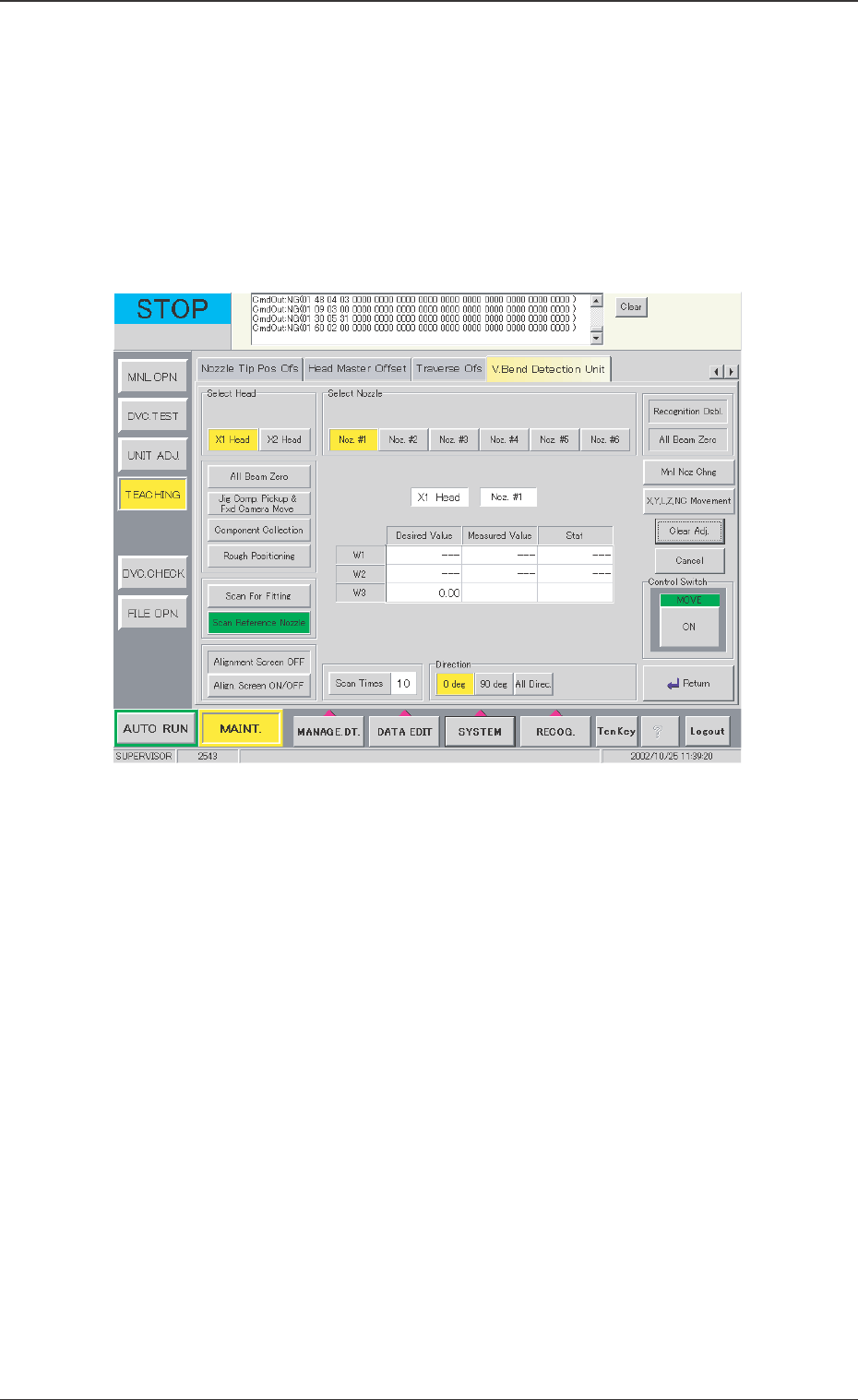
[Scan Reference Nozzle] Button
After "Scan For Fitting" operation, the reference nozzle is de-
cided. Then the reference nozzle is used to detect. As the sensor
head installation condition is found on the basis of the detections,
the sensor head position is so adjusted that it is close to the
target value.
When this button is pressed, the following window appears.
0301-001
12.1 Adjustment for Sensor Head Installation
Fig. 29 "Scan Reference Nozzle" Window

51 Tg0742-PM-SO
Operation Procedure
(1) Select the head and nozzle to be detected. Attach the
vacuum nozzle on the selected nozzle clamp.
(2) After the jig is picked up by pressing the [Jig Comp. Pickup &
Fxd Camera Move], press the [Scan Reference Nozzle]
button to start scanning.
(3) For "Scan Times", the number of detection operations is set.
Normally, set it to 6.
(4) For "Direction", the direction of the jig used for detection is
set.
This should be made at angles of both 0 deg and 90 deg.
(5) The values are compared with the installation target values,
and OK or NG is indicated for the installation condition.
Adjust the sensor head so that the indications of W1 and W3 are
both "OK".
0301-001
12.1 Adjustment for Sensor Head Installation