SOM-1655-002.pdf - 第58页
57 Tg0742-PM-SO 0301-001 12.2 Sensor Head Set and Adjustment Procedure Scan for Fitting (1) Return to the nozzle stocker all nozzles which are attached to the head. (2) Check that the "Recognition Dsbl." is not…
56 Tg0742-PM-SO
Fig. 33 "Alignment" Screen
12.2 Sensor Head Set and Adjustment Procedure
0301-001
Sensor Head Rough Positioning
(1) Place the correction jig on the jig stocker, so that its mirror
side is turned down.
(2) Return all the nozzles attached to the head to the nozzle
stocker and set the EF01 nozzle in the nozzle stocker B1-10.
Then the EF01 nozzle is set onto the head.
(3) Check that the mode is not "Recognition Dsbl.".
(4) After performing the [Jig Comp. Pickup & Fxd Camera Move]
in the "Insp Head Adj" window, press the [Rough Positioning]
button to move the correction jig to the center of the V. bend
detection sensor detecting range.
When the jig cannot easily be picked up, adjust it by
entering the approximate deviation amount in the
"Correction Jig Offset" data box.
(5) Display a graph on the monitor screen in the V. bend detection
unit by pressing the [Align. Screen ON/OFF] button.
When the [Ctrl] key is pressed twice, the monitor
screen of the V. bend detection unit appears.
(6) Loosen the set screws of the sensor head.
Roughly position the sensor head, looking the graph.
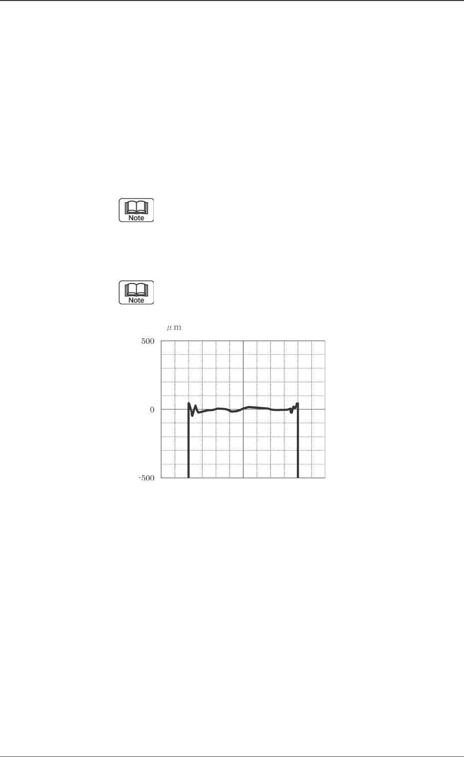
• Adjust the whole position and ω1 angle so that the graph
is shown at the center of the window. Slight vertical devia-
tion is no problem.
(7) Press the [Ctrl] key twice to return to the previous window.
(8) Close the graph display on the monitor screen of the V. bend
detection unit by pressing the [Align. Screen ON/OFF] but-
ton.
(9) Press the [Component Collection] button to return the cor-
rection jig.
(10) Set the EF01 nozzle in the nozzle stocker in the "Mnl. Noz.
Chng" window.

57 Tg0742-PM-SO0301-001
12.2 Sensor Head Set and Adjustment Procedure
Scan for Fitting
(1) Return to the nozzle stocker all nozzles which are attached
to the head.
(2) Check that the "Recognition Dsbl." is not set.
(3) Press the [Scan For Fitting] button in the "Insp Head Adj"
window and set to [All Heads] and [All Nozzles] and set the
"Scan Times" to 6 times or more. Then start scanning.
There may be V. bend recognition error, particularly
when the deviation in the ω3 direction is great.
Refer to "8. Troubleshooting after Error window
(Error ID)" for details.
Sensor Head Position Fine Adjustment
(1) Set the EF01 nozzle on the selected nozzle position of the
selected head.
(2) After the correction jig is picked up by means of pressing the
[Jig Comp. Pickup & Fxd Camera Move] button, select [Scan
Reference Nozzle].
(3) Set "Scan Times" to "6" and "Direction" to "All Direc.", and
then start the reference nozzle scanning.
(4) Confirm the data obtained for all nozzles.
· Check the ω2 data at angles of 90 deg and 270 deg for all
nozzles and make sure that all values are within the
range of ± 0.400 from the set values.
If any value is outside the range of ± 0.400, the
placement head might not have been set correctly.
• Check the ω3 data at all angles for all nozzles and make
sure that the values are within the range of ± 1.00.
If any value is outside the range of ± 1.00, the sensor
head position in ω3 direction might be deviant.
Check the sensor head attachment condition.
• Check the L data at all specified angles for all specified
nozzles and see that all values are within the range of
± 0.50.
If any value is outside the range of ± 0.50, the height
offset value for the main head might be wrong.
Check the L offset value for the main head.

58 Tg0742-PM-SO
Adjustment in
ωω
ωω
ω1 Direction
Repeatedly adjust the inclination in ω1 direction until ω1 set
condition becomes OK, using the [Scan Reference Nozzle]
function.
Adjustment in
ωω
ωω
ω3 Direction
Repeatedly adjust the inclination in ω3 direction until the ω3 set
condition becomes OK, using the [Scan Reference Nozzle]
function.
There is no problem when the ω2 set is NG (no good).
0301-001
12.2 Sensor Head Set and Adjustment Procedure