SOM-1655-002.pdf - 第55页
54 Tg0742-PM-SO Operation Procedure (1) Select the head. (2) Select the axis to be moved. (3) Select the movement direction, using the arrow buttons. (4) Select the axis movement speed. (5) Press the [ON] button and then…
53 Tg0742-PM-SO
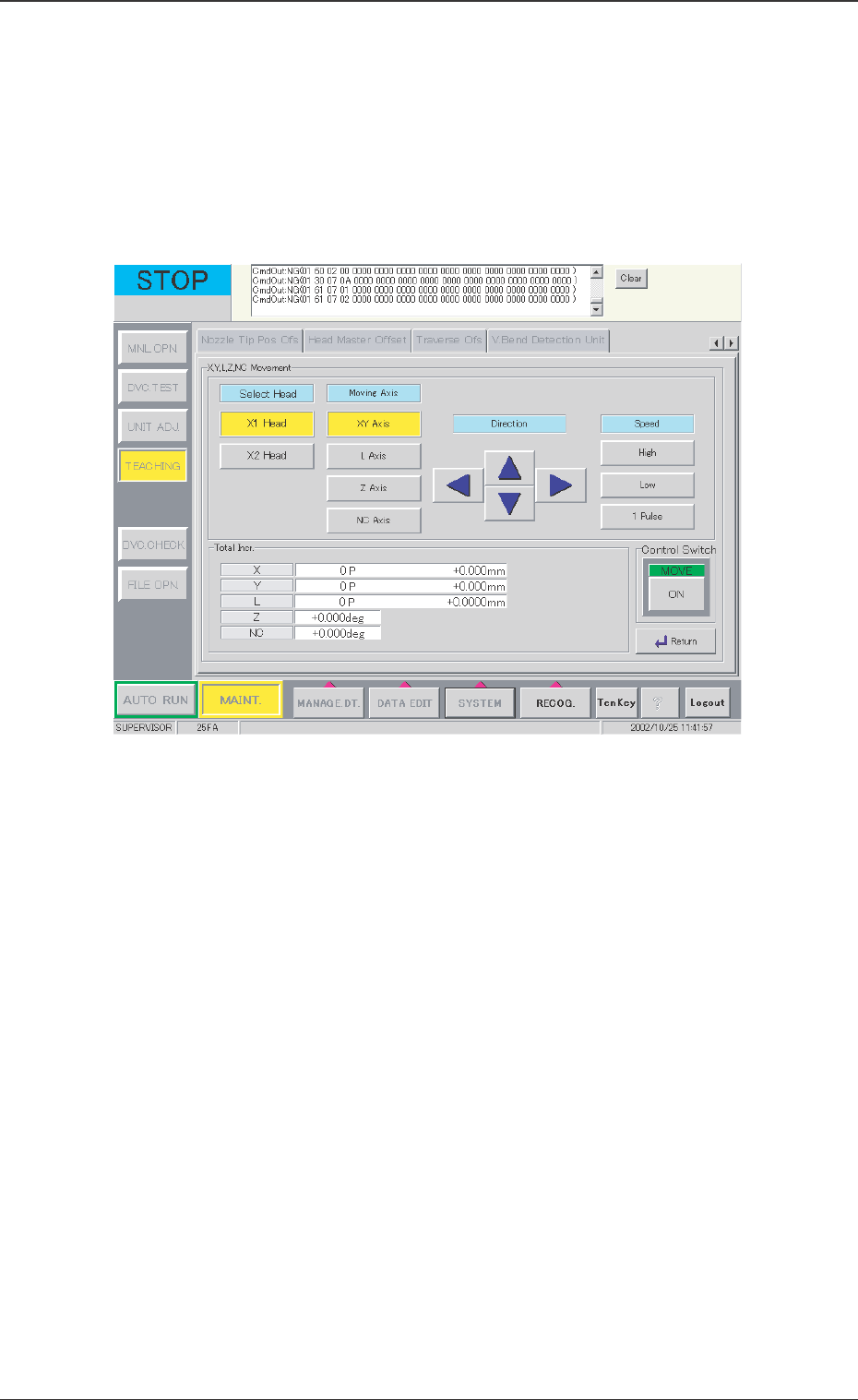
[X, Y, L, Z NC Movement] Button
This button is used when the X, Y, L, Z, or NC-axis is temporarily
moved or during rough positioning and when the position is
checked with these axes' fine movement. Before beginning such
operation, select the axis to be moved, direction, and speed.
When this button is pressed, the following window appears.
0301-001
12.1 Adjustment for Sensor Head Installation
Fig. 31 "X, Y, L, Z, NC Movement" Window

54 Tg0742-PM-SO
Operation Procedure
(1) Select the head.
(2) Select the axis to be moved.
(3) Select the movement direction, using the arrow buttons.
(4) Select the axis movement speed.
(5) Press the [ON] button and then, within 2 seconds, press the
[ENABLE] button on the operation panel.
[Clear Adj.] Button
The detected data is cleared.
[Cancel] Button
When the teaching window appears, no other operations are
available. In this case, if there is to be another operation, the
teaching function must be stopped by using this button.
[Return] Button
The previous window appears.
0301-001
12.1 Adjustment for Sensor Head Installation
55 Tg0742-PM-SO
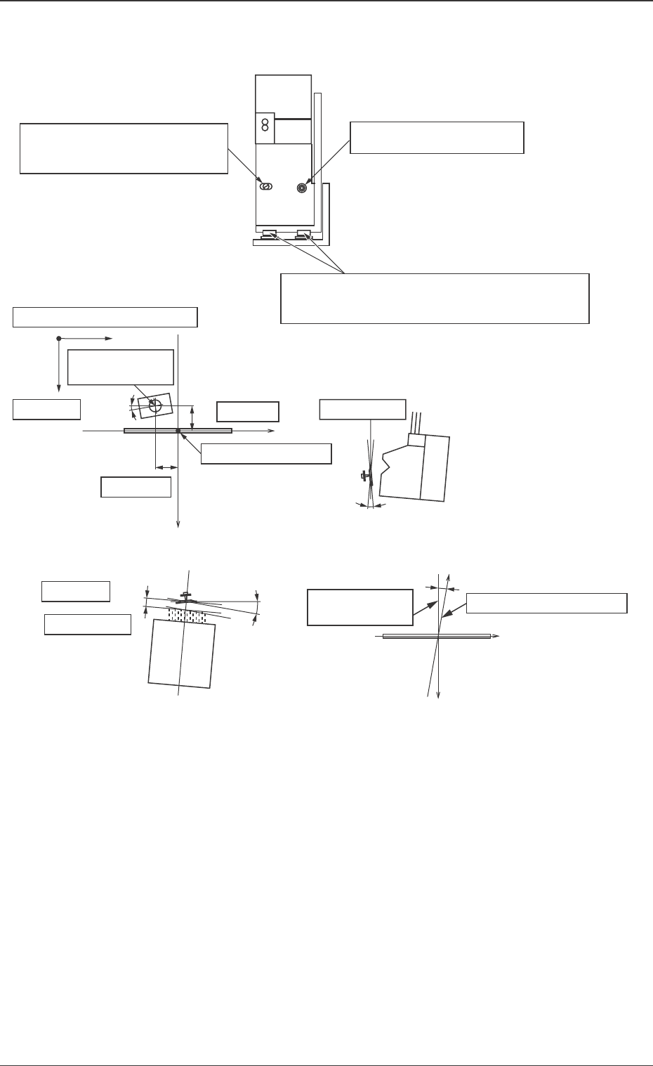
12.2 Sensor Head Set and Adjustment Procedure
12.2 Sensor Head Set and Adjustment Procedure
0301-001
Fig. 32
Nozzle Rotation
Center
Ideal Plane
dL
ω 1
L Offset
Ideal Straight
Movement Line
Actual Y-axis Movement
Center
X
Y
ω 3
y Offset
Center of Detection
x Offset
z Offset
Beam Position Coordinates
Y
dx
dy
dz
ω 2
x
Inclination ω1 can be changed
by turning the eccentric pin.
Set Screw for ω1 direction
X and Y positions and ω3 of the whole sensor
head are adjusted by loosening all set screws.
Ideal Plane