SOM-1655-002.pdf - 第39页
38 Tg0742-PM-SO [Result of V . Bend Detection] Button The detection results for each lead are displayed. When this button is pressed, the following window appears. 0301-001 10.2 "V . Bend T est" Window Fig. 20 …
37 Tg0742-PM-SO
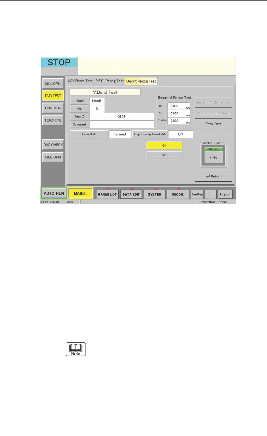
Fig. 19 "Component Recog Test" Window
[Cmpnt Recog Result Adj.] Button
Using the camera, the positional adjustment is set, based on
the component recognition results. When this button is
pressed, the following window appears.
Operation Procedure
(1) After pressing the [V. Bend Detection] button, press the
"Control SW" [ON] button.
(2) When the [MOVE] switch is pressed, the V. bend is
detected.
[Send Cmd of Dspl. Image] Button
When the [Send Cmd of Dspl. Image] button is pressed, the
command sends the detection’s resultant image to the monitor
in the V. bend detection unit.
Pressing [Ctrl] key twice switches the display to the
monitor display in the V. bend detection unit.
0301-001
10.2 "V. Bend Test" Window
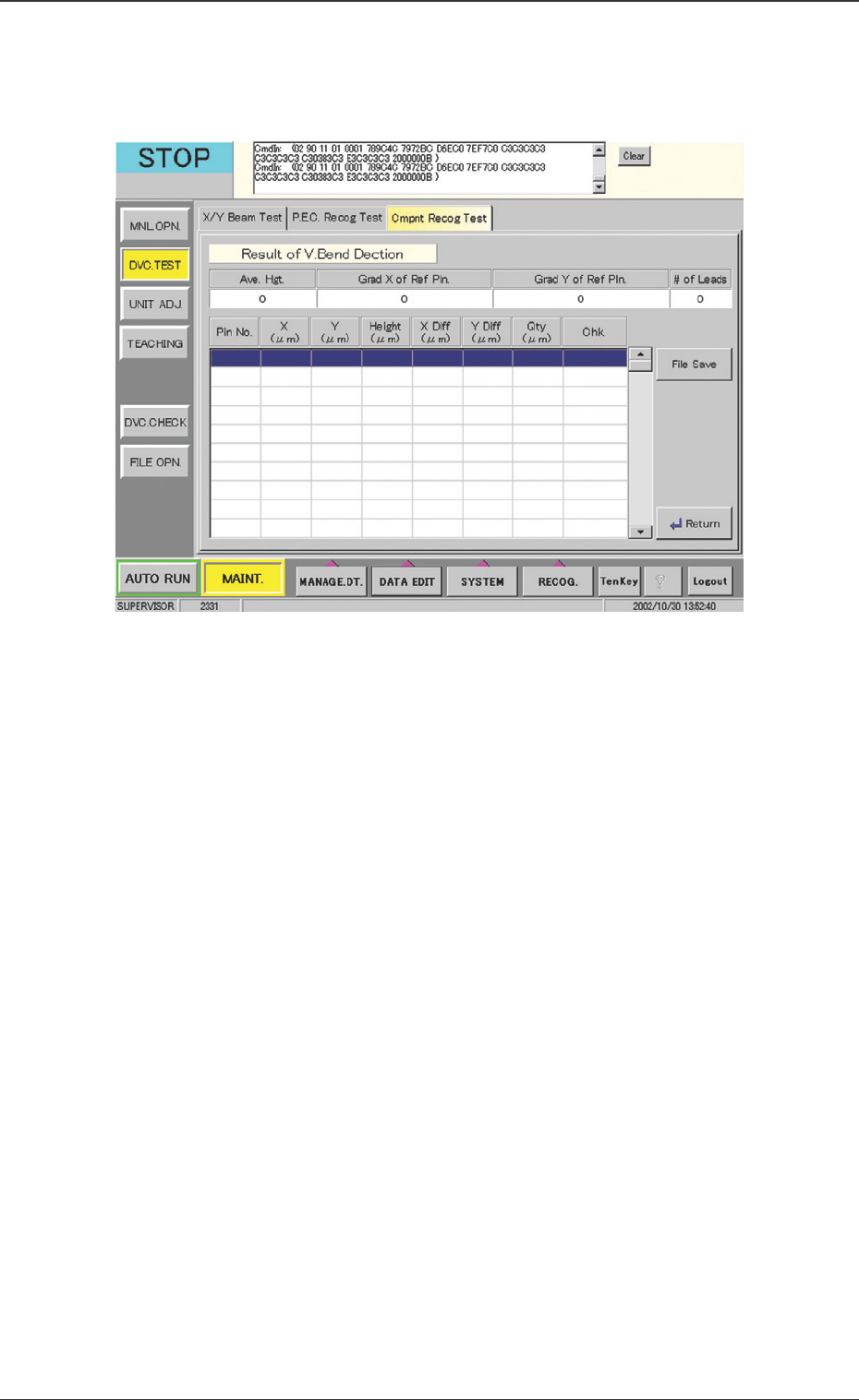
38 Tg0742-PM-SO
[Result of V. Bend Detection] Button
The detection results for each lead are displayed. When this
button is pressed, the following window appears.
0301-001
10.2 "V. Bend Test" Window
Fig. 20 "Result of V. Bend Detection" Window
V. Bend Test Result Indication
Ave. Hgt. :
The mean value of the heights of all lead is displayed.
Grad X of Ref Pin. :
The inclination in X direction is indicated as "x" which
satisfies the formula θ = Tan-1 (x/1024).
Grad Y of Ref Pin. :
The inclination in Y direction is indicated as "y" which
satisfies the formula θ = Tan-1 (x/1024).
# of Leads :
The number of leads detected is displayed.

39 Tg0742-PM-SO0301-001
Each value for X, Y, Height, X Diff, Y Diff and Qty is
shown in µm. For X and Y, the direction is the same as
that of the X-axis and Y-axis, respectively. For Height
and Qty, when the terminal is at its upper position from
the reference, the value becomes a negative or minus
value. For the Qty, the reference plane is regarded as
"0". When the terminal is found at its lower position
from the reference plane, the value becomes positive.
When the terminal is found at the upper position from
the reference plane, the value becomes negative.
10.2 "V. Bend Test" Window
V. Bend Test Detailed Result Indication
Pin No. :
The terminal No. is indicated.
X (µm) :
The positional coordinate X (component center reference)
for each terminal is displayed.
Y (µm) :
The positional coordinate Y (component center reference)
for each terminal is displayed.
Height (µm) :
The measured value for the height of each terminal is
displayed.
X Diff (µm) :
Indicates the deviation amount in direction X away from the
ideal position of each terminal. This ideal position is de-
cided based on the component size.
Y Diff (µm) :
Indicates the deviation amount in direction Y away from the
ideal position for each terminal. This ideal position is de-
cided based on the component size.
Qty (µm) :
The deviation amount from the reference plane is found,
based on XY position and heights of all terminals.