SOM-1655-002.pdf - 第18页
17 Tg0742-PM-SO 0301-001 4.Scope of Actions 4. Scope of Actions (1) The component is picked up (taken out) from the feeder . (2) The component recognition operation is performed. (3) The placement head is moved to the po…
16 Tg0742-PM-SO0301-001
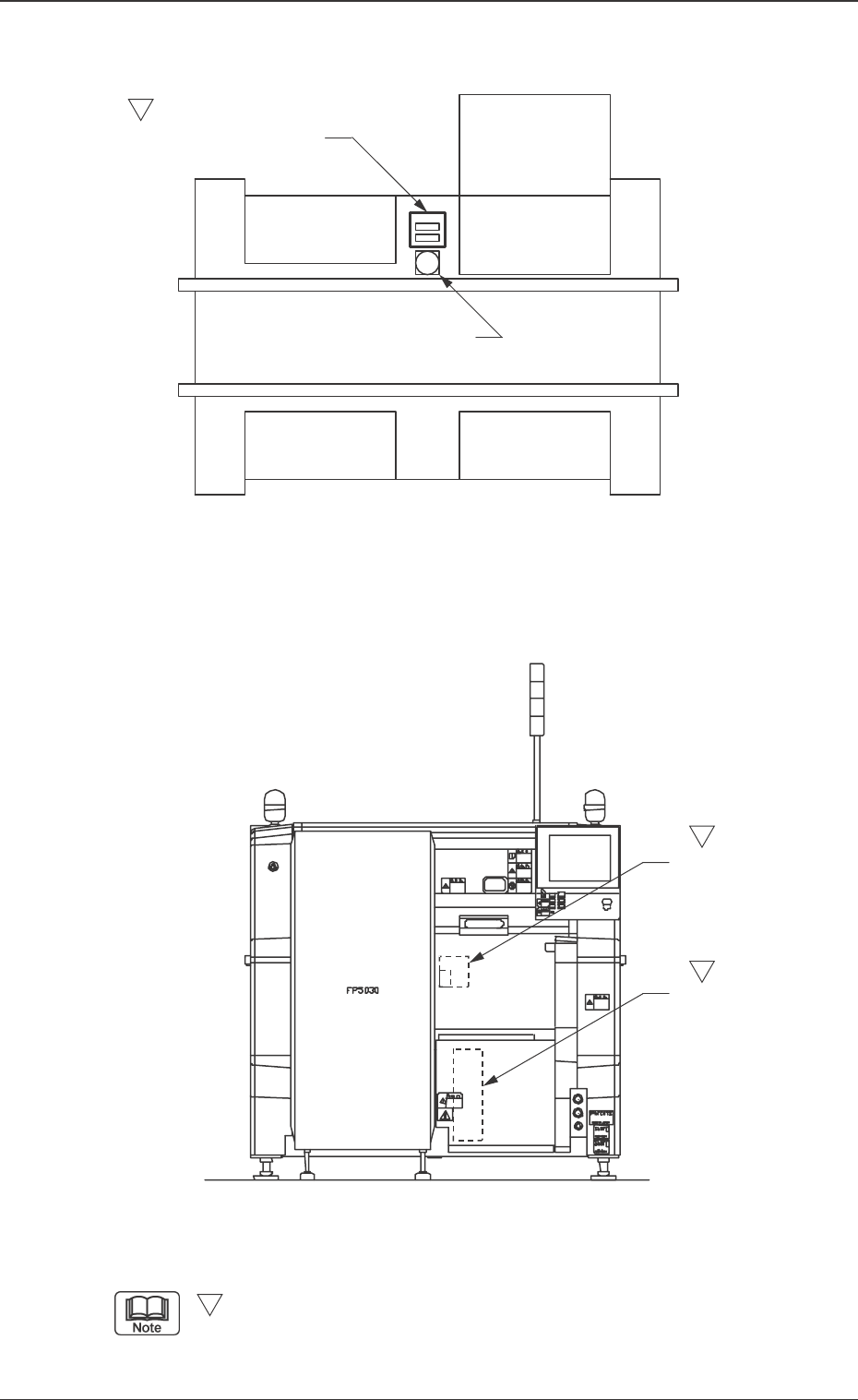
3. Rough View of Machine
Fig. 2 V. Bend Detection Unit
Fig. 1 Main Machine of TIM-X100
3. Rough View of Machine
-marked area is specially specified.
S
(Front Side of Machine)
S
S
S
V. Bend Detection
Sensor Head
V. Bend Detection Unit
Controller
Feeder Base
Feeder Base
Feeder Base
Tray Feeder
Fixed Recognition Camera
V. Bend Detection Unit
17 Tg0742-PM-SO0301-001
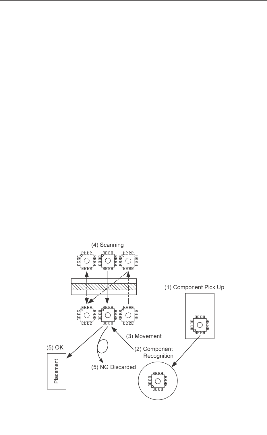
4.Scope of Actions
4. Scope of Actions
(1) The component is picked up (taken out) from the feeder.
(2) The component recognition operation is performed.
(3) The placement head is moved to the position where the V. bend
detection is performed.
• While the placement head is moving, the following actions are
performed.
The placement head stands by at the position where the scan-
ning is started.
X, Y and Z are corrected for the component to be picked up
based on the component recognition results.
The component stands by at the specified angle where the
scanning is started.
(4) V. bend detection is performed.
• Batch Scanning is employed for batch detection.
• Scanning is performed twice for divided detection.
(5) The following processing is performed based on the V. bend detec-
tion results.
OK: The component is placed.
NG: The component is discarded.
Ref. : The V. bend judgment criteria are set in the component
library.
Fig. 3
18 Tg0742-PM-SO
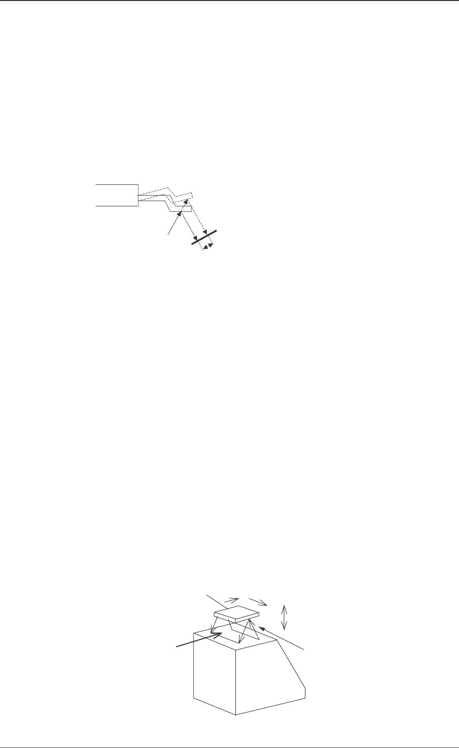
4.1 Measurement
Principle of Lead Bend Measurement
• The laser beam hits the lead and its reflection is detected at the
light receiving element.
• When the lead height is changed, the detection position on the
light receiving elements is also changed. Therefore, the lead
height is detected by obtaining the detection position on the light
receiving element.
Lead Bend Amount Inspection Procedure
• The scanning type laser displacement gauge (Infrared Laser,
Class 1) is used for lead bend amount detection.
• The successive height data of a component to be measured in
the direction X can be obtained by laser scanning of the compo-
nent in the direction X using polygon mirror.
Then, the three dimensional data on the bottom of the compo-
nent to be measured can be obtained by laser scanning of the
component in the direction Y.
The lead position is calculated based on the obtained three
dimensional data and the lead bend is inspected.
Reference : The laser beam of class 1 has been designed to be safe
for humans.
This level of beam does not damage your retina even if
you watch it for 100 seconds without blinking.
Fig. 4
Fig. 5
0301-001
4.1 Measurement
V. Bend Detection Unit
Light Receiving Element
The difference in height can be seen as the
difference in the detection position on the light
receiving element.
Laser Beam
Secondary Operation
Method in Direction Y
Chipped Component to be Measured
Direction X (Laser Operation Direction)
Direction ZLight Receiving
Movement Direction
of Component to be
Measured
Light Emitting