SOM-1655-002.pdf - 第80页
79 Tg0742-PM-SO 14. Circuit Diagrams 0307-001-(M750WC--A3101) KB/PD/VGA Connection Diagram Note (a) When the optional keyboard on the side A and the pointing device are connected, PCB UA88 should be used. (b) The -marked…
78 Tg0742-PM-SO
14. Circuit Diagrams
0307-001-(M750WH--A3101)
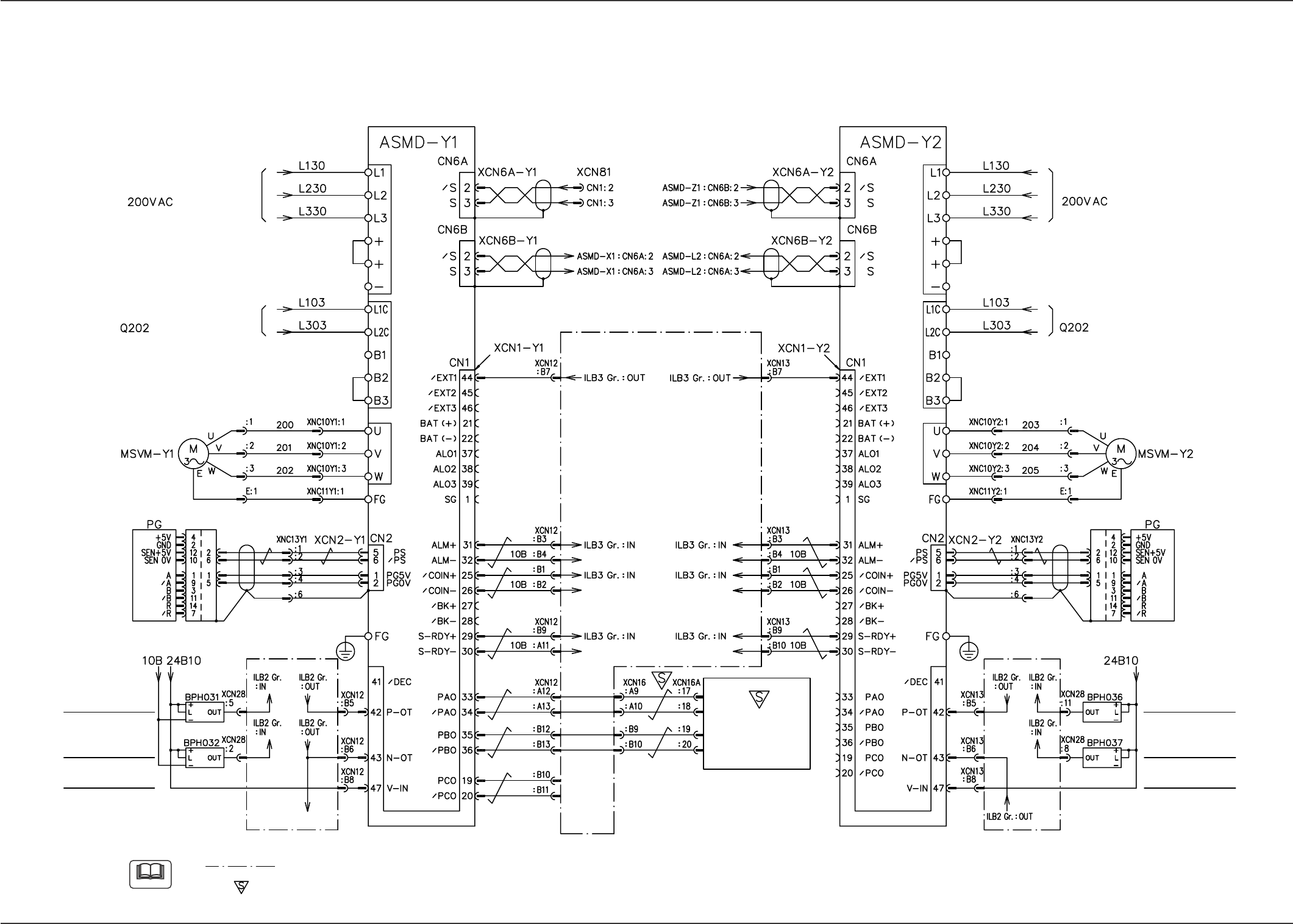
Y1- and Y2-Axis Motor Circuit Diagram
Note
(a) The diagram within broken lines shows one within I/O main board PCB (UB12).
(b) The -marked area is specially specified.
Y1-Axis External
Input Power Supply
Y1-Axis Limit (+)
Note (a)
Y1-Axis Limit (-)
Note (a)
Y2-Axis XCN13: To B6
S/P Converter
Control Circuit Power Supply
Main Circuit Power Supply
Y1 Axis Y2 Axis
To X1 Axis To X2 Axis
From Z1 Axis
From EB005
V. Bend Detection
Unit
From (Y1-Axis XCN12: B6)
Shielded Wires
Y2-Axis External
Input Power Supply
Y2-Axis Limit (+)
Y2-Axis Limit (-)
Control Circuit Power Supply
Main Circuit Power Supply
Note (a)
S/P Converter
Shielded Wires
79 Tg0742-PM-SO
14. Circuit Diagrams
0307-001-(M750WC--A3101)
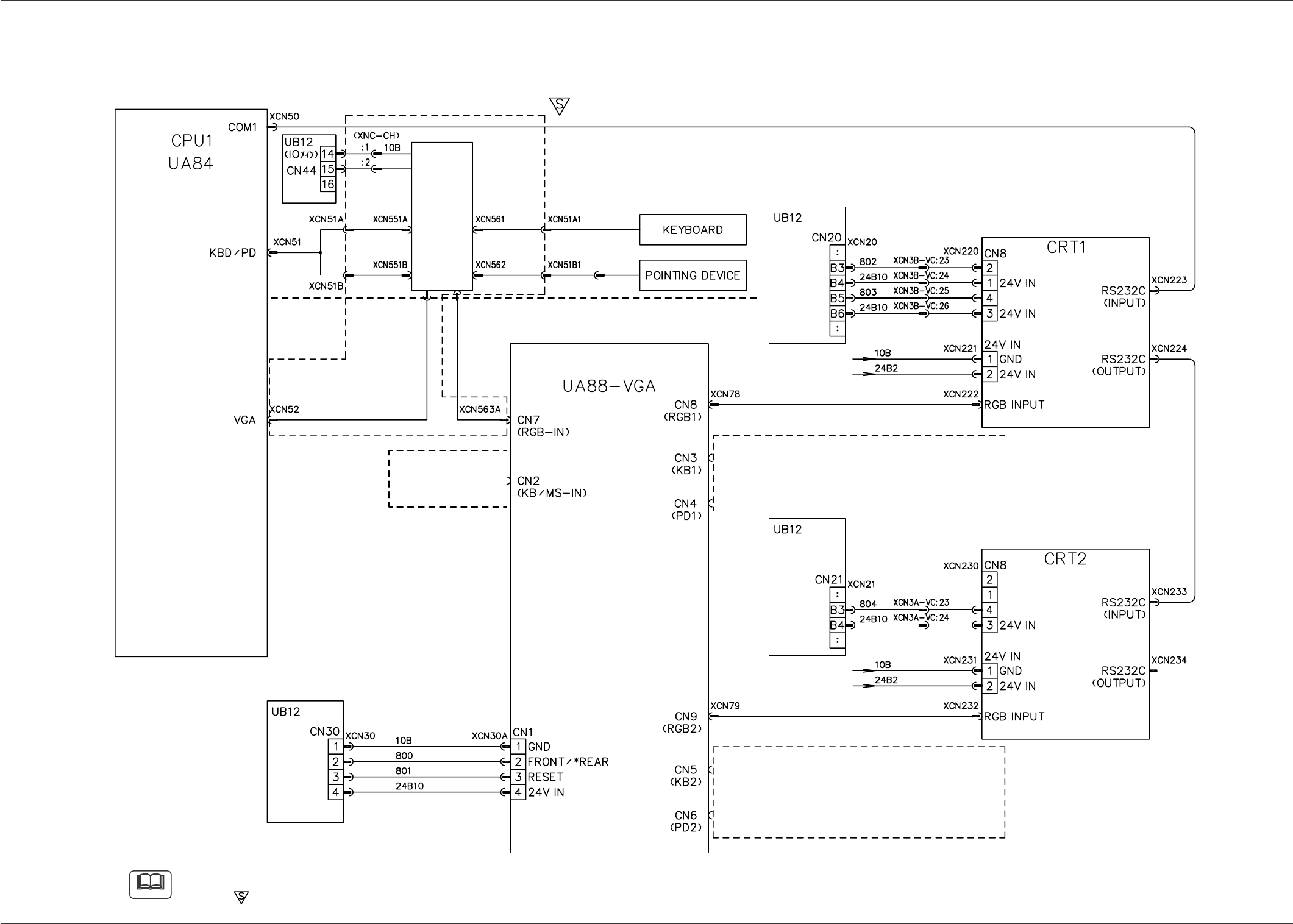
KB/PD/VGA Connection Diagram
Note
(a) When the optional keyboard on the side A and the pointing device are connected, PCB UA88 should be used.
(b) The -marked area is specially specified.
Note (a)
PC Selector
Keyboard and Pointing Device on Side B
VGA Distributor
LCD with Touch Screen on Side B
Touch Screen Invalid/*Vaild
Back Light OFF/*ON
Keyboard and Pointing Device on Side B
LCD with Touch Screen on Side A
Back Light OFF/*ON
Keyboard and Pointing Device on Side A
(Eqipped with the option)
(IOMB)
(IOMB)
(IOMB)
(in the standard specifications)
(Eqipped with the option)
(option)
80 Tg0742-PM-SO
14. Circuit Diagrams
0307-001-(M750WC--A3102)
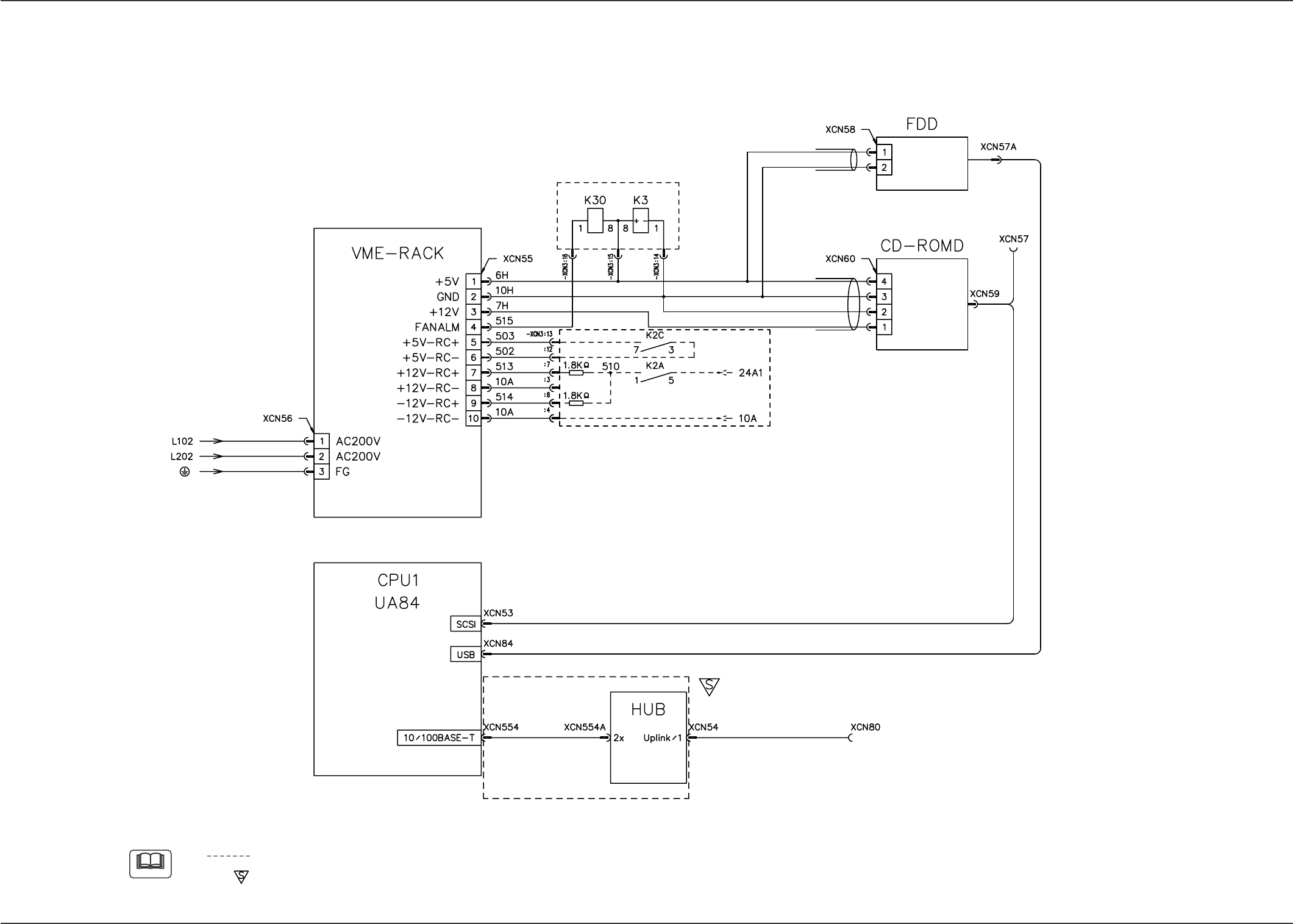
FDD/CD-ROMD/LAN Connection Diagram
Note
(a) The diagram within broken lines shows one within relay PCB (UA96).
(b) The -marked area is specially specified.
Note (a)
Note (a)
External LAN
(Termination)