SOM-1655-002.pdf - 第42页
41 Tg0742-PM-SO 0301-001 10.2 "V . Bend T est" Window [Error Data] Button When the detection result is decided as NG, the error data is displayed. When this button is pressed, the following window appears. Fig.…
40 Tg0742-PM-SO0301-001
10.2 "V. Bend Test" Window
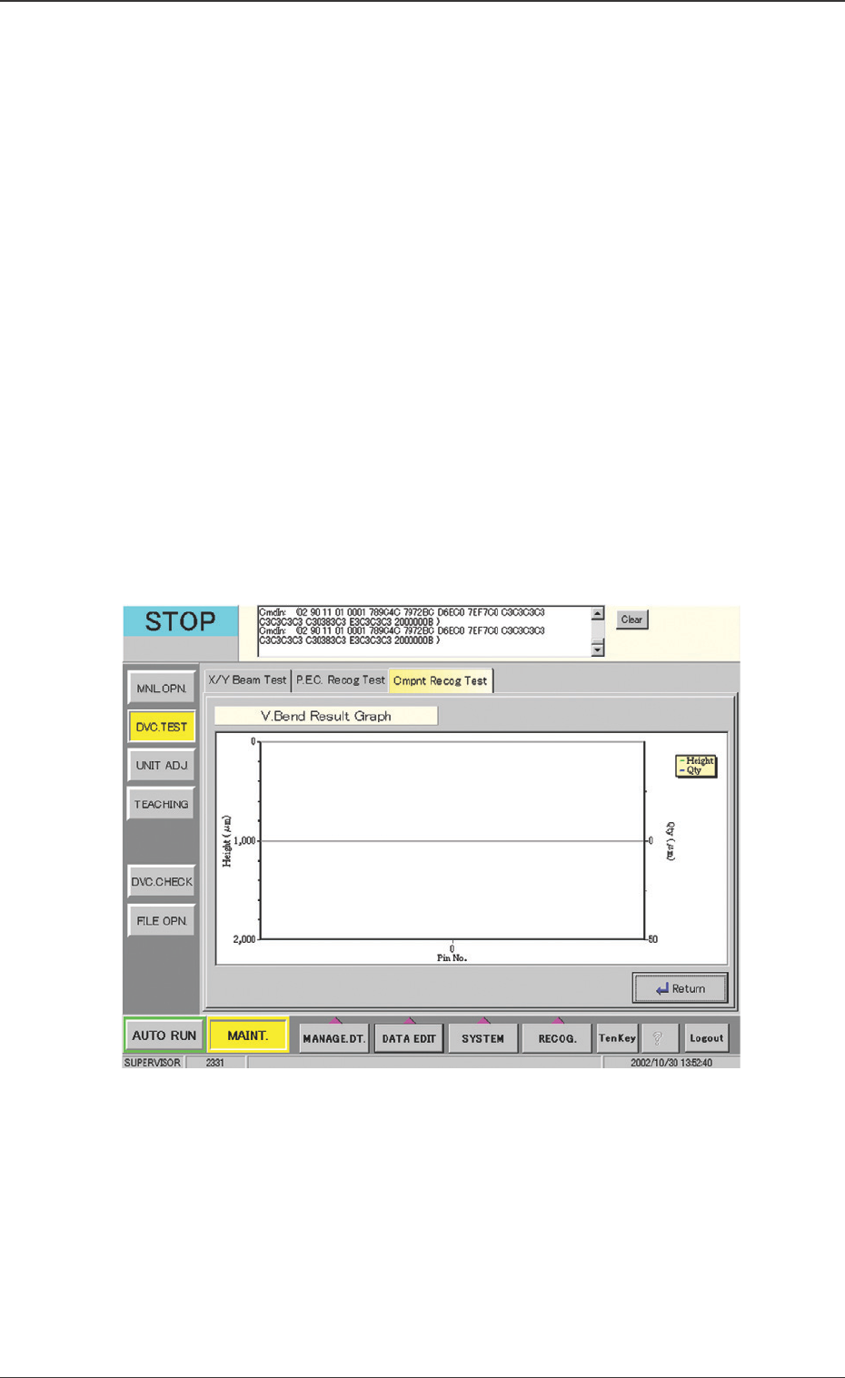
Fig. 21 "V. Bend Result Graph" Window
[File Save] Button
The results are saved in the CSV file.
CSV Format
PGH, PDX, PDY, CNO : List of overall results
889, 22, -56, 120 : Overall results
CX, CY, CZ, DX, DY, DZ, JG : List of results
5800, -8200, 930, -20, -3, -5, 0, : Results for 1 Pin
5400, -8178, 930, -20, 10, -5, 0, : Results for 2 Pin
5000, -8155, 927, -20, 23, -7, 0, : Results for 3 Pin
4600, -8145, 927, -20, 20, -6, 0, : Results for 4 Pin
4200, -8145, 929, -20, 10, -4, 0, : Results for 5 Pin
[V. Bend Result Graph] Button
The V. bend data for each terminal is graphically displayed.
The measured lead height and V. bend amount from the refer-
ence plane, are displayed.
When this button is pressed, the following window appears.
41 Tg0742-PM-SO0301-001
10.2 "V. Bend Test" Window
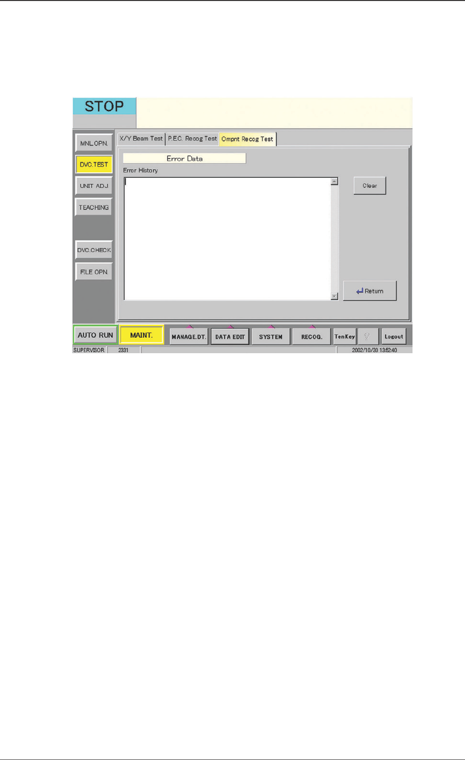
[Error Data] Button
When the detection result is decided as NG, the error data is
displayed.
When this button is pressed, the following window appears.
Fig. 22 "Error Data" Window
42 Tg0742-PM-SO0301-001
11. Operation Mode Setting
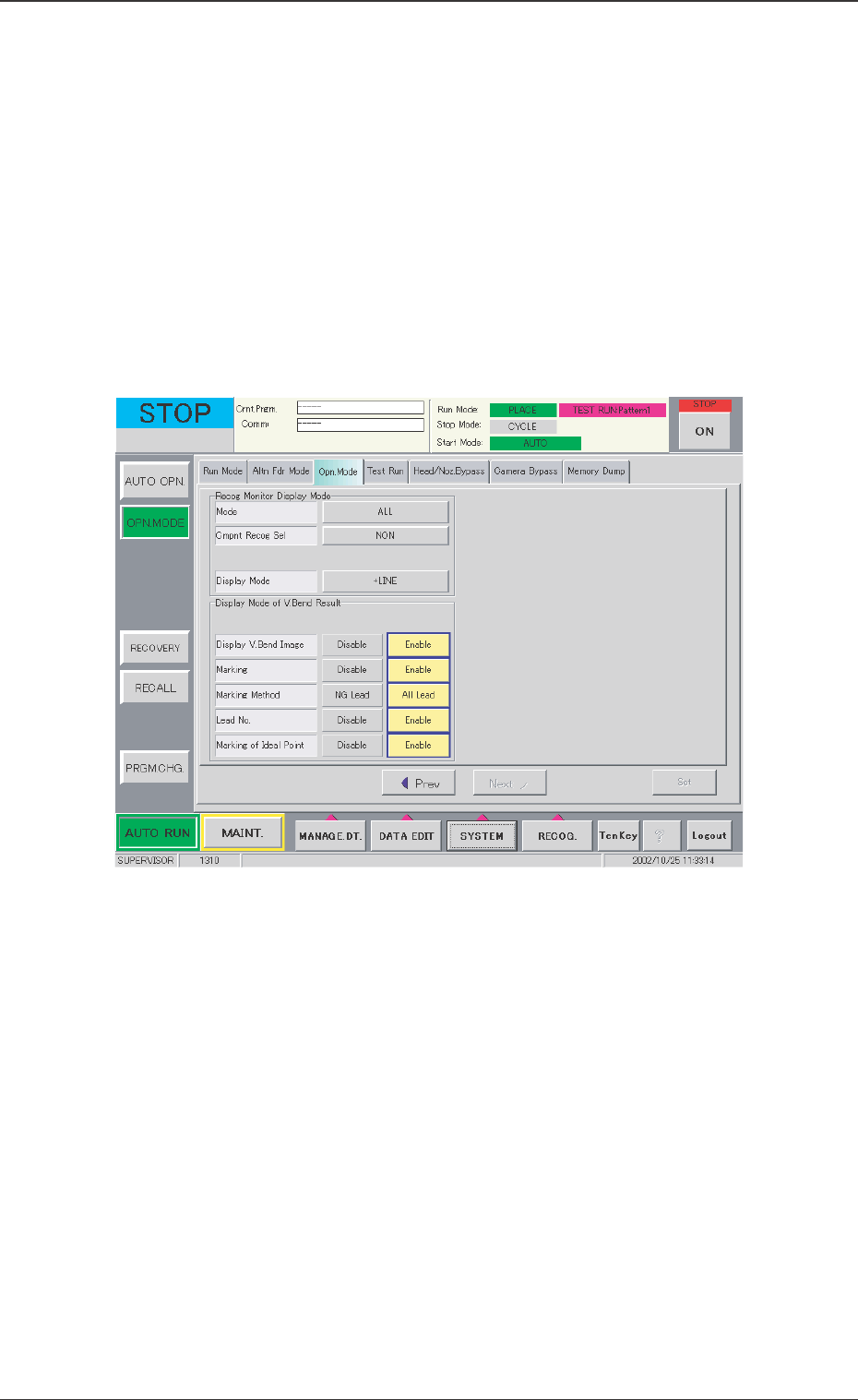
11.1 Display Mode of V. Bend Result
The settings are performed for displaying the V. bend detection
result image on the V. bend detection unit monitor.
••
••
• Sheet Layout
When the [Opn. Mode] tab in the "OPN. MODE" submenu window
and then the [Next] button are pressed, the following tab sheet
appears.
Display V. Bend Image
Disable : The V. bend image is not displayed on the monitor
in the V. bend detection unit.
Enable : The V. bend image is displayed on the monitor in
the V. bend detection unit.
Marking
Disable :The position of the detected lead is not displayed.
Enable :The position of the detected lead is displayed.
Marking Method
NG Lead : Only no good (NG) leads are marked in red.
All Lead : No good (NG) leads are marked in red and
good (OK) leads are marked in green.
11. Operation Mode Setting
Fig. 23 "Opn. Mode" Tab Sheet