SOM-1655-002.pdf - 第29页
28 Tg0742-PM-SO 0301-001 8. Troubleshooting after Error Window (Error ID) T ypical Description T able 1 Error ID Item Description 050301 Y2 Axis Data The driver data was detected outside of the possible range. (Cause 1) …
27 Tg0742-PM-SO
8. Troubleshooting after Error Window (Error ID)
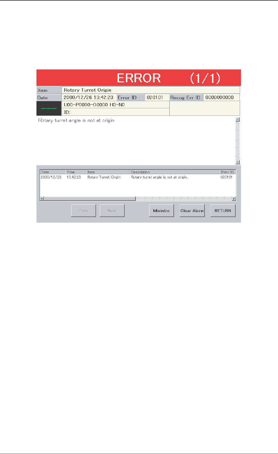
Assuming "Error ID/Item/Description" in the "ERROR" window as an
index, retrieve the related page of the instruction manual.
Refer to "Typical Description" for the detailed description.
Fig. 12 Example of "ERROR" Window
0301-001
8. Troubleshooting after Error Window (Error ID)
28 Tg0742-PM-SO0301-001
8. Troubleshooting after Error Window (Error ID)
Typical Description
Table 1
Error ID Item Description
050301 Y2 Axis Data The driver data was detected outside of the possible range.
(Cause 1) Self-Diagnostics Error Message
(Remedy 1) Zero all axes and re-start the operation.
When the machine cannot be set to its normal condition, consult our service
personnel for the remedy.
050401 Y2 Axis Limit (+) Limit error has been detected.
050402 Y2 Axis Limit (-) Limit error has been detected.
(Cause 1) The X1 axis might have overrun due to generation of noises, overcurrent, etc.
The sensor might be defective.
(Remedy 1) Zero all axes and re-start the operation.
When the machine cannot be set to its normal condition, consult our service
personnel for the remedy.
(Continued to the next page)
*1
*2
*3 *2
*4
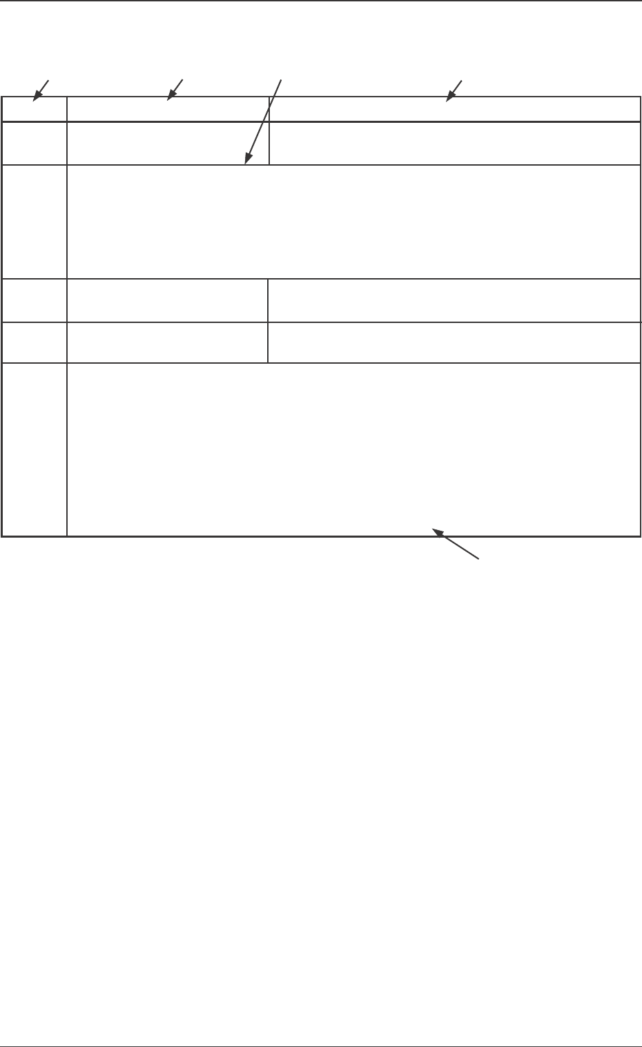
*1 The error IDs (IDs displayed in the "ERROR" window) are de-
scribed in the numerical order.
*2 Described are the classification (Item) and explanation
(Description) in the "ERROR" window.
*3 Described are the causes and remedial procedures of the errors
in "*2 (Item and Description)".
The causes and remedies are correlated as follows.
(Cause 1)
→ (Remedy 1)
(Cause 2)
→ (Remedy 2)
(Cause 3)
→ (Remedy 3)
*4 This indicates that the related contents are described subse-
quently on the next page.

29 Tg0742-PM-SO
Error ID Item
6b0101 Communication Time Out
Unit Connection (Network) Error
6b0102 Command Error
6b0103 Received Data Error
6b1001 Software Operation
Environment Error [1000]
6b1011 PC Memory Error [1010]
6b1061 Sensor Head Laser Diode Error
[1060]
6b1071 Memory Error in the Signal
Processing Board [1070]
6b1081 Sensor Cable Disconnected
[1080]
6b1091 Sensor Head Scanner
Rotation Error [1090]
6b1101 Laser OFF [1100]
6b2001
6b2011 Incorrect Command
(Height Adjustment) [2010]
6b2031 Incorrect Command (Identifier)
[2030]
6b2041 Measurement Start Time Out
[2040]
6b2051 Incorrect Command
(Parameter Error) [2050]
6b2061 Component Data Error due to
Unregistered Component [2060]
6b2071 Measurement Mode Error [2070]
6b3001 Terminal (Ball and Lead)
V. Bend Error [3000]
6b3011 Terminal Position Judgment Error
[3010]
0301-001
8.Troubleshooting after Error Window (Error ID)
Description
Check the connector cable between the V. bend detection
unit and the main machine (network cable).
The command sent to the V. bend detection unit, is not cor-
rect. If the same error still occurs after the power is turned
on again, contact our service personnel for details.
The data received in the V. bend detection unit is not cor-
rect. If the same error still occurs after the power is turned
on again, contact our service personnel for details.
The V. bend detection unit is malfunctioning. If the same
error still occurs after the power is turned on again, contact
our service personnel for details.
Memory error in the V. bend detection unit. If the same error
still occurs after the power is turned on again, contact our
service personnel for details.
The laser diode is malfunctioning. Check the sensor head
connection. If the same error still occurs after the power is
turned on again, contact our service personnel for details.
Memory error in the signal processing board in the V. bend
detection unit. If the same error still occurs after the power
is turned on again, contact our service personnel for de-
tails.
Check the connection between the V. bend detection unit
and the sensor head.
The scanner in the sensor head is malfunctioning. Check
the connection of the power cable to the sensor head.
The laser is not output. If the same error still occurs after
the power is turned on again, contact our service personnel
for details.
The V. bend detection unit is set to height adjustment mode.
If the same error still occurs after the power is turned on
again, contact our service personnel for details.
The command received in the V. bend detection unit is not
correct. If the same error still occurs after the power is turned
on again, contact our service personnel for details.
The measurement start signal is not correctly input in the V.
bend detection unit. Check the connector cable between
the V. bend detection unit PC and the main body.
The data sent to the V. bend detection unit is not correct.
Check the data in the component library to confirm that the
component shape and measurement mode are both cor-
rect.
An unregistered component is measured. If the same error
still occurs after the power is turned on again, contact our
service personnel for details.
Measure the component in high accuracy mode.
V. bend is detected. Check the bend direction (upper or
lower) of the terminal (ball, lead).
The terminal is not correctly detected. Check the position of
the terminal (ball, lead), pitch, and component size.
Table 2