SOM-1655-002.pdf - 第23页
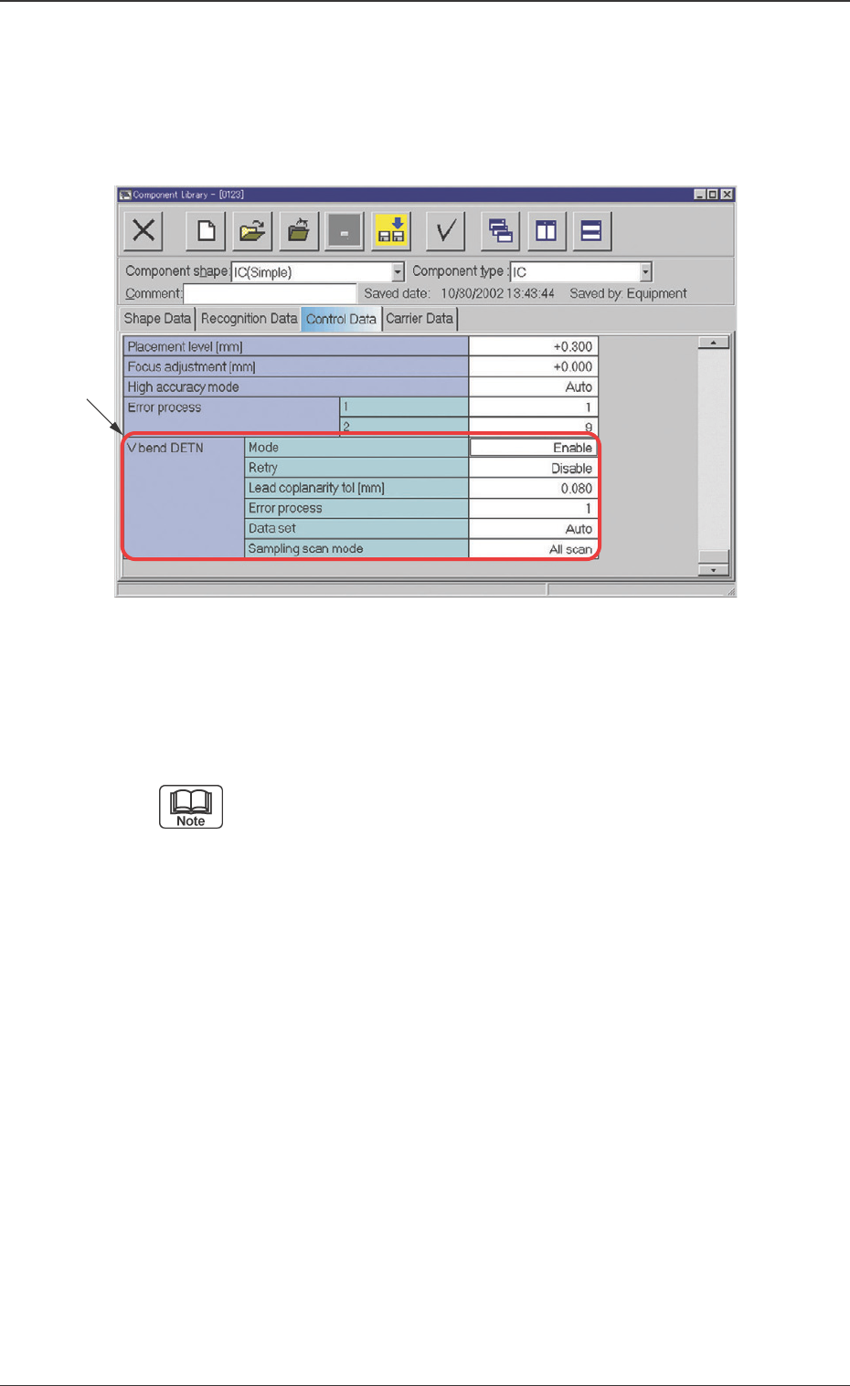
22 Tg0742-PM-SO 0301-001 Fig. 8 Example of "Control Data" T ab Sheet (IC (Simple)) 7. Component Library Error process This function is set so that, after the V . bend detection shows NG continuously , then the …
21 Tg0742-PM-SO0301-001
7. Component Library
7. Component Library
••
••
• Sheet Layout
When the [Control Data] tab is pressed, the "Control Data" tab
sheet will appear.
Fig. 7 Example of "Control Data" Tab Sheet (IC (Simple))
••
••
• Sheet Composition
This tab sheet is used for indication or entry of each data.
Refer to "4.1 Basic Operations" in "Section 2" (the instruc-
tion manual (Vol. 3) of the main machine) for the detaild
information on how to enter parameters.
*1 V. bend DETN
Mode
V. bend detection function is set.
Enable : V. bend detection function is used.
Disable : V. bend detection function is not used.
Retry
The retry function is set.
The retry function is to detect a V. bend again, with a different
setting; this when the height for scanning is deviated or the
detection result is NG (no good), due to incorrect setting in V.
bend detection operation.
Lead coplanarity tol [mm]
The tolerance of the height deviation for the Iead is set. If the
V. bend is larger than the set value, it is judged as NG (no
good).
*1
22 Tg0742-PM-SO0301-001
Fig. 8 Example of "Control Data" Tab Sheet (IC (Simple))
7. Component Library
Error process
This function is set so that, after the V. bend detection shows
NG continuously, then the machine should be stopped due to
the error.
Data Setting Range: 1 to 9
1 : When NG occurs once in V. bend detection, the ma-
chine is stopped.
2 : When NG continuously occurs twice, the machine is
stopped.
n : When NG continuously occurs "n" times, the machine
is stopped.
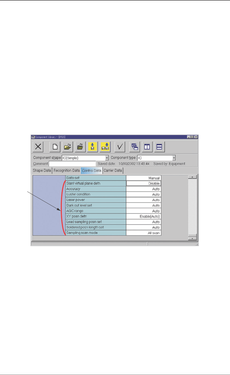
Data set
Auto : Detailed settings are automatically performed.
Manual : Detailed settings can be performed manually.
*2 Items for Detailed Setting
When the V. bend detection data setting is set to "Manual", the
detailed setting items will be displayed.
Slant virtual plane detn
Disable (Default) :
The virtual plane inclination is not to be decided on the basis
of the heights of all leads.
Enable (Manual) :
The virtual plane inclination is to be decided manually on the
basis of the heights of all leads.
*2

23 Tg0742-PM-SO0301-001
7. Component Library
Slant virtual plane allowance
This is displayed when the slant virtual plane detection is set to
"Enable (Manual)". Enter the slant virtual plane allowance value.
When "0" is set, the slant virtual plane detection will
not be decided.
Accuracy
Auto (Default) :
The measurement accuracy (standard/high accuracy) is
automatically set, based on the component data.
Standard :
The test is performed at standard-resolution level.
SOP, QFP, Connector:
This is set when the lead pitch is 0.4 mm or more.
BGA, CSP :
This is set when the ball pitch is 0.8 mm or more and the
ball diameter is 0.5 mm or more.
High accuracy :
The test is performed at high-resolution level.
SOP, QFP, Connector :
This is set when the lead pitch is less than 0.4 mm.
BGA, CSP :
This is set when the ball pitch is less than 0.8 mm and
the ball diameter is less than 0.5 mm.
Luster condition
Auto (Default) :
The component characteristics (lead luster degree) are set
automatically. In the case of leaded components, the half-
luster lead is set. In the case of BGA and CSP, the luster
ball is selected.
Luster :
The component characteristics (lead or ball luster degree)
are set to "Luster". In the case of leaded component, when
the surface is palladium- or gold-plated, the lead is strongly
reflected, set it to "Luster". In the case of the ball, "Luster"
is usually set.
Half-luster :
The component characteristics (lead luster degree) are set
to "Half-luster". With a general leaded component, set it to
"Half-luster".
Non-luster :
The component characteristics (lead or ball luster degree)
are set to "Non-luster". When the lead or ball is not a
reflected component, set it to "Non-luster".